Electro Tech is an online community (with over 170,000 members) who enjoy talking about and building electronic circuits, projects and gadgets. To participate you need to register. Registration is free. Click here to register now.
Welcome to our site! Electro Tech is an online community (with over 170,000 members) who enjoy talking about and building electronic circuits, projects and gadgets. To participate you need to register. Registration is free. Click here to register now.
Hi,
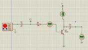
I am trying to amplify the ac input signal but any input value results in 0V output, Can anyone what's wrong with my circuit? I don't want to use a voltage divider bias configuration.
The AC input signal does not even get to the base of the transistor. It is shorted out to the +6.7 volt supply. This is assumed to be zero ohms impedance so the voltage cannot deviate from +6.7 volts. Even if the AC signal got to the base the voltage on the collector cannot change from +4 volts. You need to re-design your circuit.
I am trying to amplify the ac input signal but any input value results in 0V output, Can anyone what's wrong with my circuit? I don't want to use a voltage divider bias configuration.
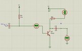
The right hand side of C2 should connect directly to the transistor base, not power.
However you will still not get any output as the collector of the transistor is also connected directly to a power source.
It needs a load resistor in the collector circuit, so the varying current through the transistor results in a varying voltage across that resistor.
That will give a an output signal from the collector.
The resistor value should be calculated so it has a voltage drop of roughly somewhere between a third and half the collector supply voltage, at the collector bias current you set.
Just a caution, direct connection of C2 to base with no emitter degeneration
will result in a lot of loading to input signal. As well pretty serious distortion
possibly, especially since circuit does not have proper bias.
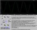
You have something that "appears" to work. That is a naive viewpoint. Let me ask you if the output waveform looks at all like the input waveform. If not, it would be more correct to call it a distortion circuit rather than an amplifier. One purpose of an amplifier is to replicate the input waveform while increasing the voltage, current, or power. Get your head out of the dark place it is in and start learning about actual circuits rather than the fever dreams you have put forth.
The first thing I was taught about biasing a transistor is to never simply use one base resistor to a supply voltage.
Because each transistor has a different current gain and has a different base-emitter voltage even if they have the same part number.
Also, the current gain increases as the transistor heats up.
Therefore a voltage divider biases the base plus an emitter resistor is added to 0V.
Sometimes a biasing resistor is connecting between the collector and base for negative feedback.
Variations in bias due to temperature and beta may be reduced by moving the VBB end of the base-bias resistor to
www.electricalengineering.xyz
Related
Why is voltage divider bias a more stable bias than a collector feedback bias?
I have to make some assumptions about what you are really asking. There are 2 major ways to bias a bipolar junction transistor (BJT). The first is with a resistor in the emitter and a voltage divider to the base. Works great. The emitter resistor raises the input impedance and controls the gain. The second way is to connect a resistor between the collector and the base with the normal collector pull-up resistor to Vcc. Also works great. This method lowers the input impedance and controls the gain.
Guys Thanks for all your replies. Really appreciated. atferrari why I don't want to use voltage divider bias is because I want to test fixed bias configuration first.
Second I identified the mistake myself later and corrected the circuit and it finally worked with some different values.
Is there any book available that precisely focuses on circuit explanation? like what each component does etc
not just the basic theory.
This site uses cookies to help personalise content, tailor your experience and to keep you logged in if you register.
By continuing to use this site, you are consenting to our use of cookies.