EdStraker
Member
I am a hobbyist, and have dabbled in electronics for many years. An engineer I am not. I have made the "standard" 555/4017 sequencer circuit many times and in many forms. but I am stumped for a solution on this one.
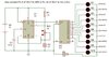
In the "standard" configuration, the decade counter performs the Q0-Q9 count with one led on at a time. My question is, is there away to configure this circuit to have all LED's on, and perform the Q0-Q9 count turning the LED's off one at a time? And with minimal additional parts as space is at a premium with this particular project.
have attached a basic "standard" config schematic for reference.
My appologies for such a mundane first post. Thanks in advance for anyone who can assit me with this project.