Continue to Site

Welcome to our site!

Electro Tech is an online community (with over 170,000 members) who enjoy talking about and building electronic circuits, projects and gadgets. To participate you need to register. Registration is free. Click here to register now.

  • Welcome to our site! Electro Tech is an online community (with over 170,000 members) who enjoy talking about and building electronic circuits, projects and gadgets. To participate you need to register. Registration is free. Click here to register now.

Cascade 4026 ICs?, and what are

Status
Not open for further replies.

grrr_arrghh

New Member
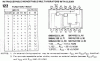
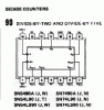
what are HD74LS90P and SN74L122N ICs?

also, if i drive a 4026 Ic with a 555 astable at 100Hz, then cascade the 4026 into another, then another, will this be accurate enough to make the final 4026 count in seconds?

thanks

tim
 
If Your circuit no battery operated, take the 100Hz time-base from mains trafo(after two-way rectifier) for better accuracy.
 

Attachments

  • 122.gif
    122.gif
    80 KB · Views: 948
  • 90.gif
    90.gif
    26.5 KB · Views: 935
hmmm, makes sense, but it has to be portable (so, power from batteries),

and

also I need all three 4026, because I need to display 1/10 seconds and 1/100 seconds aswell.

thanks anyway

tim
 
In this case apply a quartz time-base oscillator with a cheap 32,768kHz watch-quartz. (possible canibalize the complete time-base from old LCD wristwatch.... The LCD backplane signal easy to find on PCB, it's 32Hz)
 
32KHz oscillator components

That's a great idea for a general timebase, Sebi. You can find LCD watches at any dollar store in the U.S. At the very least, you get a 32KHz Xtal for much less than the minimum order cost (+ shipping) at most electronics distributors. A little probing will probably result in a suitable timebase. It's cheap and fairly accurate for a 1 second timebase (or some other integer divisor of 32Hz). The watch circuit isn't much use for 1/10 or 1/100 second intervals unless it has a stopwatch function. - CAL
 
thanks, but err what?

ermm, how do i recognise a 32Khz Xtal, and how would i go about building it into the circuit. A stopwatch type device is exactly what i am trying to make...

tim
 
Since you are using a battery, the 32kHz crystal is probably the best choice. but you will need to have a prescaler to divide your signal by 320 first so that you get 100ths and 10ths of seconds. You would then need some discrete logic to divide by 32 (not too difficult). You could easily accomplish this with far less parts if you could use a microcontroller and good crystal in your circuit.
 
timebase source

A 32KHz crystal really means 32.768KHz (a power of 2). To get an accurate 1 second timebase, just divide by 2^15. It isn't possible to get 1/10 sec or 1/100 sec exactly, the best you can do with an integer divisor is come close (32.768KHz/328 = 99.90Hz, 32.768KHz/3277 = 9.999Hz). Those values are probably close enough for what you had in mind. The error is small, but fixed and can't be adjusted out (the 99.90Hz timebase would have an error of +10 mS for every 10 seconds timed).

32KHz isn't the best crystal frequency to start out with if you're trying to produce a precise 0.1 or 0.01 second timebase. You can use a 1 second output along with a PLL multiplier to get the 0.1 and 0.01 outputs, but that adds more complexity. Starting out with a crystal frequency that's divisible by decade values may be simpler. Your original plan with a 555 running at 100Hz is fine, too. It just depends on how accurate & precise you want the stopwatch to be.


The 32KHz crystal is the tiny cylindrical metal can with two leads (some types also come in an oblong metal casing).
 
hmm

okay

crystals sound a bit too complicated for me. I am only an "Electronics Newbie". Maybe I'll just stick to the 555 IC. Does anyone know the accuracy of this after the pulses have been cascaded three times?

Thanks for everyone's help.

Tim
 
stopwatch

the 555 sounds good Tim, crystals just make a more stable and precise timebase. Digital divider stages don't add inaccuracy, it all comes from the oscillator source. You'll probably want a trimpot in the 555 circuit to adjust it's output frequency. It will be easier to calibrate if you make the pot a small part of the overall resistance (it's only needed to trim the oscillator frequency by a slight amount, enough to compensate for the tolerance errors of the timing components - R1, R2 and the cap). Pick R1 + 2R2 values to have a period slightly under 100Hz, then add in a small-valued pot for trimming.
 
what you say all makes sense, and thanks

would you recomend using a trimming cap aswell?, or do I put the cap in, then adjust the pot to compentsate for the incaccuracy? I will prob use two preset pots for the resistors, and a multimeter to make sure of them...

p.s. you don't happen to know the exact values of the resistor and the cap to make 100hz...?, or how i can work them out.

the pic below shows the type of astable i am using. I reckon that if Ra=7K, and Rb=150K, and C=47nF, I will get 100.01Hz..., which is prob near enough, but i'm not sure what accuracy that will give, after, say, 10secs? ahhhh brain ache. School maths lessons should teach us stuff like this, its much more useful


**broken link removed**

Thanks everyone, i'm not sure what i'd do without u
 
stopwatch timebase

a trimming cap isn't needed. It looks like you already have the right equation for the 555. Do you have access to a frequency or period counter? That would allow you to calibrate the timebase more accurately. Again, you may want to make the pots just a small part of the overall resistance, trimming will be easier that way.
 
don't have access to a frequency or period counter (any way i can easily make one?).

are caps accurate enough then?

thanks

Tim
 
Status
Not open for further replies.

Latest threads

New Articles From Microcontroller Tips

Back
Top