Continue to Site

Welcome to our site!

Electro Tech is an online community (with over 170,000 members) who enjoy talking about and building electronic circuits, projects and gadgets. To participate you need to register. Registration is free. Click here to register now.

  • Welcome to our site! Electro Tech is an online community (with over 170,000 members) who enjoy talking about and building electronic circuits, projects and gadgets. To participate you need to register. Registration is free. Click here to register now.

car instrument cluster

Status
Not open for further replies.

trigger

New Member
can someone please tell me if you use a schmidt trigger sn74ls14 with a 6v input through a 1n4005 diode , will the max output be 5v. I am hooking it up to a sst89c54 microcontoller chip and don't want to blow the port. The signal is coming off a speedometer. Any help with the calculations to find the speed to display on an lcd will be appreciated
 
7400 series power

If I understand correctly...
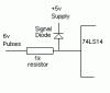
You have some tacho-type pulse train which is 6v or more, this is to be fed through a 74LS14.
You wish to use a 1N4005 diode in series with its output thus making use of its 0.7v forward bias :?:

If the 74LS14 is correctly supplied with 5v then its output will not exceed this voltage (unless severely abused) so the 1N4005 will not help here.
The input to the 74LS14 could be damaged by the 6v pulses so this point should be protected...
Take the pulse signal through a 1k resistor to the 74LS14 input and have a diode (a signal diode will do - 1N914 or something?) from this point to the positive 5v supply, this will 'clip' the input voltage to something safer.
See diagram below.

For the calculation ...
You need to know the pulse-rate of your sensor system, if the sensor is on a wheel and produces one pulse per revolution then the wheel's circumference will tell you the distance per pulse.
If the sensor is in a gearbox somewhere then you must try to establish how many pulses per wheel rev you get, or the distance per pulse (whichever suits you).
If the distance per pulse is known then it is easy to get the pulses per unit distance (km?) - this is the divisor for your calculation.
OR
Time between pulses can be measured and speed calculated from that (1/time = speed) - you need to allow for (and cope with) 1/infinity and you still need a multiplier based on distance/pulse.

Hope that helps ...
 

Attachments

  • InputProtect.gif
    InputProtect.gif
    1.7 KB · Views: 1,315
Hi, I'm also looking to make an automotive application similar to this, except I want to make a Tachometer with an LED or LCD display. Preferably LCD display with some time of shift light device as well. I'd like to use a microcontroller (processor? not sure if there's a difference).

Your reply will help with the 1st part of the project since the Hall Effect sensor on a Ford puts out a 12V high pulse train so I'll have to knock that down.

Any good places to go to get started with figuring out how to do the counting and LCD displaying? or any info?

Derek
 
Status
Not open for further replies.

Latest threads

New Articles From Microcontroller Tips

Back
Top