Continue to Site

Welcome to our site!

Electro Tech is an online community (with over 170,000 members) who enjoy talking about and building electronic circuits, projects and gadgets. To participate you need to register. Registration is free. Click here to register now.

  • Welcome to our site! Electro Tech is an online community (with over 170,000 members) who enjoy talking about and building electronic circuits, projects and gadgets. To participate you need to register. Registration is free. Click here to register now.

Car camera test station issue - need help

Status
Not open for further replies.

krisbl

New Member
Gentleman hi to everyone.

I am new here and someone of you might be able to help me with the issue that i have.

We have station for Car Camera Testing, testing is done thru a video receiver connected to a software - where camera during testing reads QR code and shows eitheer PASS or FAIL.

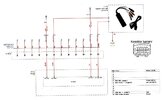
On the attached diagram you can see the complete circuit of the testing protocol.

Now the problem is, XC connector is wired at our facility. And often the workers missplace the wires places between pins 5 and 12 on the XC.

Both of the wires are ground, and even with missplaced wires the test passes - but on later stage when the camera got installed on the car shows problem.

I need to invent some solution that will prevent the camera to go ON if those two wires are missplaced on the connector - or to fail the test.


I need to sort this out, as i am in Maintenance there and my job depends on it.
AND TO BE HONEST HAVE NO IDEA WHAT TO DO.


THANK YOU IN ADVANCE,
KRIS


P.S. i have also posted the same thread on AAC, you can check the same https://forum.allaboutcircuits.com/threads/car-camera-test-station-issue.191389/
 

Attachments

  • Screenshot_20230112_230640_Adobe Acrobat.jpg
    Screenshot_20230112_230640_Adobe Acrobat.jpg
    145.9 KB · Views: 274
You need to tell us what is the difference between the wires that get crossed over?
What is the problem when the camera is in use?
I assume that AMV Video+ (pin 6) is supposed to be associated with AMV Video Ground (pin12, next to pin 6)
I would measure the capacitance between pin 6 and pin 5, and between pin 6 and pin 12, on both a correctly wired cable and an incorrectly wired cable. You will need a sensitive capacitance meter, that goes down to 10 pF or less. The results may give you some clues what you can test in production.
 
Bud, thank you for your replay and time considering.

I just do the measurements, so:
Between pin 5 and 6, and 6 and 12 i can not read any capacitance with my metter.
Is something means to you on resistance both between 5/6 and 6/12 shows 76.90 ohm.

My metter measures other way arround capacitance between 11 and the rest four of the pins 1.860 uF.


For your reference im attaching photo of the camera including extention cable (as that is how it goes to the test station and to the car itself).

As you can see on the photo, the GREY connector is the one where operators when installing the connector change places of the brown wire with the black one and vice-versa.


Tnx
20230123_203753.jpg
20230123_203806.jpg
 
Gentleman hi to everyone.

I am new here and someone of you might be able to help me with the issue that i have.

We have station for Car Camera Testing, testing is done thru a video receiver connected to a software - where camera during testing reads QR code and shows eitheer PASS or FAIL.

On the attached diagram you can see the complete circuit of the testing protocol.

Now the problem is, XC connector is wired at our facility. And often the workers missplace the wires places between pins 5 and 12 on the XC.

Both of the wires are ground, and even with missplaced wires the test passes - but on later stage when the camera got installed on the car shows problem.

I need to invent some solution that will prevent the camera to go ON if those two wires are missplaced on the connector - or to fail the test.


I need to sort this out, as i am in Maintenance there and my job depends on it.
AND TO BE HONEST HAVE NO IDEA WHAT TO DO.


THANK YOU IN ADVANCE,
KRIS


P.S. i have also posted the same thread on AAC, you can check the same https://forum.allaboutcircuits.com/threads/car-camera-test-station-issue.191389/

hi,
One solution to this problem could be to add a circuit to the testing protocol that specifically checks the connection of the wires between pins 5 and 12 on the XC connector. This circuit could include a comparator that compares the voltage levels of the two wires and triggers a fail message on the software if the wires are found to be miss-wired. Another solution would be to install a dedicated connector for the ground wires, which will prevent the miss-wiring of ground wires as the connector will only allow the correct wiring. Consider implementing a visual aid, such as color-coding or labeling, on the wires and the connector to make it easier for workers to identify and correctly connect the wires.
 
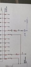
I'd try adding a series resistor with parallel to the pin 5 video ground connection in the test rig?
eg. 1K with 10uF across it.

That should hopefully have little effect on the video, but should also prevent the camera operating if it is cross connected and that pin is being used as power ground.
 
I'd try adding a series resistor with parallel to the pin 5 video ground connection in the test rig?
eg. 1K with 10uF across it.

That should hopefully have little effect on the video, but should also prevent the camera operating if it is cross connected and that pin is being used as power ground.
The problem is that the ground wires are being interchanged. One is the power ground, and one is the ground reference for the video output.

I don't know what the difference is electrically, or why it matters if they are interchanged.
 
I don't know what the difference is electrically, or why it matters if they are interchanged.
From the drawing, the connector has camera power and ground, then video signal and its ground/screen (presumably in to coax at some point in the end use).

If the screen and power ground pins are swapped, it would presumably mess up the video quality when connected to a long coax?

My idea is to prevent the camera operating (at the test bench) if it's trying to use the video ground for power return due to a cross connection.
 
Multimeter can't usually measure capacitance with the resolution you would need for this. You would need to use a meter that can measure to 10 pF or better, something like this:- https://uk.farnell.com/b-k-precision/bk890c/capacitance-meter-hh-50000uf/dp/2932315

What goes wrong when the incorrectly-wired camera is installed in a car?

I will try to find a capacitance meter to measure those values.

As in my initial post, if the BLACK and BROWN wires got missplaced- at our facility the test again PASSES as both the wires are negative loop inside the camera (brown supose to bring negative to the camera from the power source and black to give negative from the camera to the reader/com or whatsoever)

But once placed on the actual car, as the same camera is used as side mirror cammera for creating 360 degree view of the vehicle the same doesnt work.
I assume that is due to the vehicle system CanBus or simillar.
 
OK, the two grounds must also be solidly connected in the camera...

All you can do is make a separate cable test rig, that verifies pin-to-pin between the two ends of the connecting cable.
 
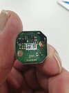
This is the inside of the camera

On the connection points goes flat cable, spring attached - continuing with the black cable on the photos above.
 

Attachments

  • IMG-7a008a413cf734da17c4ab131ddc81e8-V.jpg
    IMG-7a008a413cf734da17c4ab131ddc81e8-V.jpg
    111.9 KB · Views: 240
If i add 4007 diode on the brown wire the image is good, if i add the same to the black wire the image starts to move and shows some lines.

Is this of any help ???
 
If you mean, can the messed up image with diode on the black wire - be used as starting point for solution YES.

AS i said earlier i need eitheer the image to go messed up or to be shut completely in order the test to fail.


But can't use it as is now, because as long the diode is on pin 12 no matter you put the black or brown wire the video is messed up. And i need it when the brown is on 5 and black on 12 test to pass, and when vice-versa to fail the test.
 
Status
Not open for further replies.

Latest threads

New Articles From Microcontroller Tips

Back
Top