Continue to Site

Welcome to our site!

Electro Tech is an online community (with over 170,000 members) who enjoy talking about and building electronic circuits, projects and gadgets. To participate you need to register. Registration is free. Click here to register now.

  • Welcome to our site! Electro Tech is an online community (with over 170,000 members) who enjoy talking about and building electronic circuits, projects and gadgets. To participate you need to register. Registration is free. Click here to register now.

Capacitor charge time - How to calculate this

Status
Not open for further replies.

Exo

Active Member
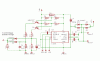
This is a part of the scematic for a sattelite position system i'm desiging.
However I don't realy know how to calculate the required value for C6.

I'll try to expain first
It's part of a schort-circuit / overload protection. The resistors in chain R1 - R2 are calculated so they activate Q1 on a short circuit (+7.5A). This will cause the system to be deactivated immediately. No problem here...
But the second chain (R3 - R4) are for overload protection. (+2.5A) This signal needs to be delayed (by C6) so the system will not deactivate by the motors higher startup current...

First of all, does anyone know how long the startup of such an engine will take... It's rather hard to measure as the peak is already gone before the meter shows something...

then, Assuming Q2 is saturated and R13 - R14 are 10K each, what's the formula to calculate C6 to give a certain delay T...
 

Attachments

  • motordriver.gif
    motordriver.gif
    17.9 KB · Views: 812
I think you will need to do some testing, and pick a value. You will likely find that these motors will spin-up to a steady current in about 1/2 second, depending on the gear ratio. You will find that things like wind load and colder/hotter temperatures will change the delay required. I have used similar actuators, mine had clutches built in that could be set for torque, but we needed to protect against shorts. We just loaded a motor, a little above where the clutch ( removed ) slipped, got an average measurement and went with that. This gave us protection against mechanical failure or icing on the lead screw or in the gearbox.

Very interesting circuit by the way, the SGS chip looks like something I may use on new designs involving the actuators I use. Right now I am controlling the motors with ST OmniFet's the VP04n04 , logic level drive, over voltage/current/temperature.
 
Well, you can calculate the charge time using some calculus.

If you look up "RC time constant" or "Calculating capacitor charge time" theres a bunch of sites that attempt to explain the calculation. If you can make sense of it. I can't, I'm not that far along in my studies.
 
Assuming Q2 is saturated and R13 - R14 are 10K each, what's the formula to calculate C6 to give a certain delay T...
The answer depends on the value of +VM, the threshold voltage of the Schmitt trigger, and the value of R17. The Schmitt threshold is dependent on the logic family and its supply voltage.
Why do you have two PNP sense transistors, and then proceed to OR the outputs with diodes? You only need one transistor and you don't need the diodes.
Answer those questions and we can answer yours.
 
Hmm..Ron H makes a good point, hadn't really noticed that. I guess you are trying to sense 2 different fault conditions. Shorts, and overloads in the motor. I would simply go for the lower of the 2 ( overload ) and decide that in the case of an overload you shutdown the bridge. Since one "trip-point" will always occur before the other, the second serves no purpose. This would simplify the calculations, to where you only need to know what current level is too high, and how long you will sustain this current before shutting down.
 
Ron H said:
Assuming Q2 is saturated and R13 - R14 are 10K each, what's the formula to calculate C6 to give a certain delay T...
The answer depends on the value of +VM, the threshold voltage of the Schmitt trigger, and the value of R17. The Schmitt threshold is dependent on the logic family and its supply voltage.

VM = 30V and R17 = 100K.
But I'm actually looking for a general formula, not just a solution, so I can make my own calculations.
I know how to calculate a normal RC, but the problem is that not all current trough R13 will go to the capacitor, some of it will get away trough R14 and R17. so how does one compensate for that?
 
zevon8 said:
Hmm..Ron H makes a good point, hadn't really noticed that. I guess you are trying to sense 2 different fault conditions. Shorts, and overloads in the motor. I would simply go for the lower of the 2 ( overload ) and decide that in the case of an overload you shutdown the bridge. Since one "trip-point" will always occur before the other, the second serves no purpose. This would simplify the calculations, to where you only need to know what current level is too high, and how long you will sustain this current before shutting down.

The reason I'm using 2 sensing circuits is because I want an overload detection for my motor, wich has to be delayed in response so it will not act on the high startup current.
The second chain is for a short circuit, in wich case i want the system to be deactivated immediately...

If i use only 1 detection i should eighter make a low treshhold (2.5A) with a delay, because it will act on the startup current. When a real short happens the delay will take to long and my H-bridge might get damaged.

Or... I should use the high treshhold, without delay but in this case it will not shutdown if the dish gets jammed
 
If you really want two thresholds, you won't be able to tell which one tripped unless you get rid of the diode OR and use two Schmitt triggers.
In the general case, you need to select R13 and R14 so that the voltage at their junction does not exceed the supply voltage (VCC) on the Schmitt trigger. If you make them equal (you suggested 10k), then you need a VCC of at least 15v (+VM/2). Another option is to connect a diode from their junction to VCC, cathode to VCC, to limit the voltage swing. Having said all that...

[edited to distinguish between Vtr and Vtf]
For the trip point Toc (overcurrent sense),
Rp*C6=-Toc/[ln(1-Vtr/Vf)]
Where Rp=R13*R14/(R13+R14),
Vtr is the rising Schmitt threshold voltage,
Vf=Vm*R14/(R13+R14).
This assumes no OR'ing diodes, and no R17.

Select the resistors first, calculate Rp and Vf, then calculate C6 to give you the desired Toc.

****************
For the release point Trel (overcurrent condition has ended),
R14*C6=-Trel/[ln(Vtf/Vf)]
where Vtf is the falling Schmitt threshold voltage.
Or, solving for Trel,
Trel=-R14*C6*ln(Vtf/Vf)
Because R13 is not involved in the discharge time constant.
 
Ron H said:
If you really want two thresholds, you won't be able to tell which one tripped unless you get rid of the diode OR and use two Schmitt triggers.

I don't need to know what triggered the shutdown. It just needs to do so before something gets damaged...

Thanks for the formula's :)
 
I guess that means you are planning a longer time constant for overcurrent than for stall current (?). If you leave in the diodes and R17, the equations will still be close. They would get pretty complex if you wanted exact values. A close approximation would be to put R17 in parallel with R14 in the equations, then assume that Vt is 0.6v higher than the actual Schmitt rising threshold. Those subtleties will probably get obscured by component tolerances and Schmitt threshold tolerance anyway.
 
Just as a practical insight, where I work we use almost the same actuators, but they are 12v, powered from the vehicles batteries ( large trucks .) We have found that it is better to sense overload, and shutdown, then to try and detect the difference between short and overload. Since the temperature range the circuit is exposed to is from summer to winter, part tolerances ( mainly capacitors and the motor itself ) have made it very difficult to get the circuit to be accurate. ( as Ron H has pointed out ) We once went so far as to heat the control box with a power resistor during the winter.

In our case we just used resistance wire creating a small shunt resistor, and measure the motor current. A small delay of about 250 mS was added, then if the condition still existed, the H bridge was shutdown. We oversized the FET's in the bridge to withstand a short-term overload.
 
Its just for extra safety. The datasheet of the L6203 bridge says that the ic can endure a non-repetitive 10A peak for less then 1ms...

that's what the second detection is for, as a last line defense, shutting everything down immidiately (hopefully faster then 1ms) when the current comes to close to 10A... (on a short probabely)...

The first detection is just to guard the motor, sattelite position motors shouldn't draw more then 2.5A. so it should shutdown on > 2.5 with a delay. This delay should be 100mS or so to enable the motor to start.
but if there were a real short then this 100mS delay would be far too long for my H-bridge...
 
Status
Not open for further replies.

Latest threads

New Articles From Microcontroller Tips

Back
Top