Continue to Site

Welcome to our site!

Electro Tech is an online community (with over 170,000 members) who enjoy talking about and building electronic circuits, projects and gadgets. To participate you need to register. Registration is free. Click here to register now.

  • Welcome to our site! Electro Tech is an online community (with over 170,000 members) who enjoy talking about and building electronic circuits, projects and gadgets. To participate you need to register. Registration is free. Click here to register now.

Can't get this 12V to 300V circuit to work! Breadboard pictures included!

Status
Not open for further replies.

Randy13

New Member
Hey guys,

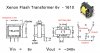
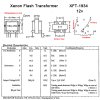
I just got all the parts in and I've been trying to build this (seemingly) simple circuit, and I've been trying to get it to work for literally 6 hours! The circuit uses the 6v (XFT-1610) transformer, and I've replaced it with the 12V (XFT-1934) transformer for use with 12v input voltage.

I cannot seem to get more than 1-2 volts out of it, while it should be stepping up to 300 volts!

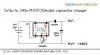
I've marked the pins of the transformer in red on the circuit picture below to make it easier to follow what I've done:

° Transformer Pin #1 connected to +12V input, as well to Pin #3 through a 1K resistor.

° Transformer Pin #2 connected to the "negative" side of 300V film capacitor.

° Transformer Pin #4 connected to 2SD882 Collector.

° Transformer Pin #5 connected to 2SD882 Base.

° 2SD882 Emitter connected to -12V input, as well as to "positive" side of 300V film capacitor.

Am I doing anything wrong? I can't seem to get more than a 1-2 volt output. ANY help or ideas would be highly appreciated!

Click on the pictures to make them larger:

**broken link removed**

Thank you so much!
 
I would have thought the input should be a/c, or at least pulsed....

If you take a look at **broken link removed**, it uses the same type of transformer (the 6V one instead of the 12V one I'm using) to boost 4 AA batteries to 300V for use as a photo flash.. :)
 
hi,
Its a Transformer Blocking oscillator.

I have drawn the windings on this image, excuse the poor quality of the windings...

Looking at your images, it shows the transistor legs bent to a 0.2inch pitch.???

Are the base pins of the transformer also inserted on 0.2inch pitch.??

If yes it looks as though you have the transistor inserted incorrectly.??

By using a 12V transformer instead of a 6V transformer it may not be providing sufficient base feedback to cause oscillation.

E.
 

Attachments

  • gDbhWEcl-1.jpg
    gDbhWEcl-1.jpg
    24.9 KB · Views: 451
So it only makes HV when the power is switched off ? The cap has to be polarised and the + is on the ground side...

I'm using a film capacitor. Do I need to use a polarized capacitor for this to work?


hi,
Its a Transformer Blocking oscillator.

I have drawn the windings on this image, excuse the poor quality of the windings...

Looking at your images, it shows the transistor legs bent to a 0.2inch pitch.???

Are the base pins of the transformer also inserted on 0.2inch pitch.??

If yes it looks as though you have the transistor inserted incorrectly.??

By using a 12V transformer instead of a 6V transformer it may not be providing sufficient base feedback to cause oscillation.

E.

The legs of the transformer were not bent at all, but the transistor legs were bent a little to fit into the correct breadboard terminals to be in line with the correct transformer pins, to avoid using jumper wires. The legs being bent in the transistor wouldn't make a difference in the operation of the transistor, would it?

If you look at this page, he sells both 6V and 12V transformers. I just assumed that I could replace the 6V transformer with a 12V transformer in this circuit to get the same output, since I have +12VDC input and not +6VDC input. Do I need something else to cause more base feedback to cause oscillation?

Also, **broken link removed** is a photo of the 6V transformer's windings, if that helps you any..?

I'm extremely new to all of this and I'm learning as I go. Thank you both very much for your help! :D
 
hi,
The pin out of the two transformer images you have posted are different.:D

Who put the RED pin numbers on the drawing I added the windings too.??

E
 

Attachments

  • 1610-spec.jpg
    1610-spec.jpg
    51.5 KB · Views: 660
  • gDbhWEcl-1.jpg
    gDbhWEcl-1.jpg
    24.9 KB · Views: 352
I did, so that I could explain what I connected to each pin.. sorry! :eek:

hi Randy,
np.:D

So which of the two transformer drawings are you actually using, just to confirm.??

E

EDIT:
looking at your link , the pins for the 6V and 12V look different, we need a schematic for the 12V version.
 
Yes!! but its not polarized..... I know that very small generated currents get away with small polyester caps, but the web site specifically said.
Make sure the cap is the correct polarisation, or it wont work
 
Ian, Non polarised caps are fine. If it says to make sure the cap is the correct polarisation it is saying that you shouldn't connect it backwards.

Nigel, the 12v transformer seems to have the same arrangement of pins (albeit different spacings). Your drawing of the secondary winding is not correct. http://ebaytoday.ru/catalog/Cameras...ng/Flash_Lighting_Kits/110945635892-item.html

from what I can see the layout looks correct. Could be a problem with the bias resistor/current as Nigel said; may be too large or too small. Or the transistor may have been damaged...
 
hi dougy,
Do you mean me , not Nigel.?:rolleyes:

Eric
 
Ooops, yes ... that would make more sense...
 
Ooops, yes ... that would make more sense...

hi d,

Ref the txr pin outs I looked at the photographs on the link to compare the 6V and 12V, one showed 3 pins and the other 2 pins,, it could be just the view angle that was different, dunno.

E.
 
I'm not clear on what you meant.. The diagrams for the two transformers show the coils to be in the same configuration for both transformers. Each has two pins on one side and three on the other. The footprint is different (pin spacings different) between the two.
 
dougy83 has a point regarding identification of windings.

Here's another sheet of the same.

Ramesh
 

Attachments

  • 1934-spec.jpg
    1934-spec.jpg
    134.7 KB · Views: 663
dougy83 has a point regarding identification of windings.

Here's another sheet of the same.

Ramesh

hi Ramesh,

I initially thought the 'red' numbers on the OP's diagram had been added by the transformer manufacturer, in fact they were added by the OP.

As the OP had incorrectly numbered the pins, it made my winding drawing incorrect.:(

Eric
 
Status
Not open for further replies.

Latest threads

Back
Top