Continue to Site

Welcome to our site!

Electro Tech is an online community (with over 170,000 members) who enjoy talking about and building electronic circuits, projects and gadgets. To participate you need to register. Registration is free. Click here to register now.

  • Welcome to our site! Electro Tech is an online community (with over 170,000 members) who enjoy talking about and building electronic circuits, projects and gadgets. To participate you need to register. Registration is free. Click here to register now.

Can't get a small CRT display to focus

Galgso

Member
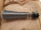
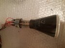
I have a 2AP1 CRT (datasheet attached) that I wish to use to make an oscilloscope eventually. The CRT was bought off Ebay and may potentially be faulty although the seller claimed that the CRT was fully functional. The main issue I am having is that I cannot get the beam to focus at all. To make sense of the following information, please note that I have the grid connected to 0v and that the cathode is positive with respect to the grid. I did this to avoid needing a split supply.

Here are the DC voltages across the various electrodes, all referenced to the grid:
Cathode: 0v (the screen is completely invisible at 20v)
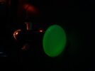
Anode 1: 200v (varying this from 80v to 540v seems to change the focus somewhat but there is nothing vaguely resembling a dot. See image 2)
Anode 2: 1kV
D1: 40v (Adjusting this seems to help make the shape on the screen more focused to some extent)
D2: 0v
D3: 20v (at 80v the beam is completely prevented from reaching the screen and the screen becomes dark)
D4: 0v
Heater (separate supply, not referenced to grid): roughly 6.3v DC

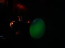
The issue is that I cannot get anything vaguely resembling a dot. I don't know if my adjustments are correct because I just see a giant blob on the screen and all I can tell when I twist the knobs on my supplies is that something is changing.

An additional issue is that the screen is pretty dim. I initially had A2 at around 500v and thought that was the reason it was dim so I brought in my other supply which goes up to a higher voltage and set it to 1kV which did help but not the extent I thought it would. It might look bright in the pictures attached but that is in near complete darkness; in a well-lit room I can hardly tell that the display is on.
 

Attachments

  • 2ap1.pdf
    92.6 KB · Views: 59
  • Image2.jpg
    Image2.jpg
    1 MB · Views: 66
  • Image1.jpg
    Image1.jpg
    1 MB · Views: 71
  • crt.jpg
    crt.jpg
    2.1 MB · Views: 85
Solution
I thought you meant higher than the first anode which is at 260v?

No, each anode and the plates need to be (considerably) higher then the previous one in order to accelerate the electron beam.

I've currently got D2 at 520v and D1 at around 20v. The whole screen is glowing faintly (looks very similar to "Image1.jpg" in the original post with the 2AP1). The glow is unfortunately too dim to capture with my phone's camera.

What voltages are on A1 and A2?, you mentioned 900V on A2 in the first post, if so 520V is FAR too low for the deflection plates, they want to be 1000V or so. Also, having a 500V difference between D1 and D2 is going to deflect the beam off the screen, even if it is working. You want D1, D2, D3 and D4...
Well I've just accidentally connected the heater to 30v DC and it was only a few seconds before the heating element failed open :-(

I hope the gods of electronics forgive me for wrecking a beautiful 1958 CRT with my stupidity (2AP1s went into production in the 40s if I'm not mistaken but my particular device says 10/58 on the packaging).

If all goes to plan I will be getting a similar CRT soon though and if there are any issues I'll post in this thread again.
 
Last edited:
I'm back with another CRT. This time it's a Mullard DG7-5 (datasheet attached). I'm still having the same issue with getting the display to focus except this time I can't see anything at all on the screen.

In the "Pic1.jpg" file attached to this post you can see a dim green glow on the inside of the tube so it is definitely doing something but I can't get the beam to converge on the screen. Also it may not be apparent in the photos but the heater is definitely connected to power (fixed 6v AC from an isolation transformer, I'm not risking burning the heater filament again) and is glowing.

This time, I am using a more conventional set-up with the cathode connected to 0v. All electrode voltages with respect to the cathode are listed below:

Grid: 0v currently, connected to a 0-30v DC supply. Raising this voltage makes the green glow dimmer. The positive side of the supply is tied to the cathode and the negative side is connected to the grid.
Anode 1: 260v DC changing this affects the green glow but I can't tell whether it is moving it or extinguishing it because it dissapears into the coated area with where the Aquadag coating is
Anode 2: 900v DC changing this affects the brightness of the glow
D1 : 0v DC (I tried sweeping it from 20v to around 280v DC and saw no effect)
D2 : 0v DC (I tried sweeping it from 20v to around 280v DC and saw no effect)
D1' : 0v DC
D2' : 0v DC
Heater : 6v AC
with the other side connected to 0v (bonded to cathode inside the CRT)

Questions:
Does anyone have any ideas as to how I can get the beam to focus?

Also, when power is initially connected the heater filament glows very brightly before settling on a lower brightness. I imagine that this is normal and occurs because it is essentially just an incandescent lamp and the resistance is lower initially before it heats up but I just want to confirm that this is not an issue because I don't want to burn the heater again and have to buy another CRT.
 

Attachments

  • Pic2.jpg
    Pic2.jpg
    1.6 MB · Views: 37
  • Pic1.jpg
    Pic1.jpg
    1.6 MB · Views: 37
  • dg7-5.pdf
    336.3 KB · Views: 33
Last edited:
I'm back with another CRT. This time it's a Mullard DG7-5 (datasheet attached). I'm still having the same issue with getting the display to focus except this time I can't see anything at all on the screen.

In the "Pic1.jpg" file attached to this post you can see a dim green glow on the inside of the tube so it is definitely doing something but I can't get the beam to converge on the screen. Also it may not be apparent in the photos but the heater is definitely connected to power (fixed 6v AC from an isolation transformer, I'm not risking burning the heater filament again) and is glowing.

This time, I am using a more conventional set-up with the cathode connected to 0v. All electrode voltages with respect to the cathode are listed below:

Grid: 0v currently, connected to a 0-30v DC supply. Raising this voltage makes the green glow dimmer. The positive side of the supply is tied to the cathode and the negative side is connected to the grid.
Anode 1: 260v DC changing this affects the green glow but I can't tell whether it is moving it or extinguishing it because it dissapears into the coated area with where the Aquadag coating is
Anode 2: 900v DC changing this affects the brightness of the glow
D1 : 0v DC (I tried sweeping it from 20v to around 280v DC and saw no effect)
D2 : 0v DC (I tried sweeping it from 20v to around 280v DC and saw no effect)
D1' : 0v DC
D2' : 0v DC
Heater : 6v AC
with the other side connected to 0v (bonded to cathode inside the CRT)

Questions:
Does anyone have any ideas as to how I can get the beam to focus?

Also, when power is initially connected the heater filament glows very brightly before settling on a lower brightness. I imagine that this is normal and occurs because it is essentially just an incandescent lamp and the resistance is lower initially before it heats up but I just want to confirm that this is not an issue because I don't want to burn the heater again and have to buy another CRT.

You are perfectly correct, a valve heater is VERY similar to an incandescent light bulb, and in just the same way it initially lights up brightly until it warms up and the resistance increases.

As far I'm aware the defection plates need to be at a higher voltage than the focus anode, so only running them at such a low voltage may well give you no spot on the screen.
Thanks for the reply I'll try connecting both plates to a higher voltage later today and report back
 
In addition to what Nigel says, connect the deflection plates to your 260 volt supply through four resistors (ie one resistor to each deflection plate).
Make the resistors 47k to 100k in value.

JimB
 
In addition to what Nigel says, connect the deflection plates to your 260 volt supply through four resistors (ie one resistor to each deflection plate).
Make the resistors 47k to 100k in value.

JimB
What are the resistors for? I'm in no position to question your knowledge; I'm just curious. My resistors are rated for 250v so I suppose I'll need 8 resistors in total.
 
What are the resistors for?
Just an excess of caution, it feels like a good thing to do in an unknown experimental situation.

My resistors are rated for 250v so I suppose I'll need 8 resistors in total.
Just use the four resistors.
The voltage rating refers to the voltage across the resistor.
In this case there should be no current flowing in the resistors so the voltage across the resistor should be zero, it does not matter that the whole resistor is sitting at 260 volts.

if you feel uneasy about this, just give the resistors a miss.

JimB
 
Just an excess of caution, it feels like a good thing to do in an unknown experimental situation.


Just use the four resistors.
The voltage rating refers to the voltage across the resistor.
In this case there should be no current flowing in the resistors so the voltage across the resistor should be zero, it does not matter that the whole resistor is sitting at 260 volts.

if you feel uneasy about this, just give the resistors a miss.

JimB

Sorry Jim, but I'm a bit confused as to their purpose? - and 260V is probably far too low for the deflection plates, which presumably need to be higher than the focus anode?.

Assuming they are intended for potential current limiting?, I've no problem with that (other than there won't be any current), but 260V sounds far too low.
 
Sorry Jim, but I'm a bit confused

I think that I am all messed up in my head with this one.

I have been looking at an ancient circuit diagram of a spectrum analyser which used a DG-7-5 CRT.

The cathode and grid sit up at around -1000 volts
The focus anode appears to be adjustable between -955 an -460 volts
The second anode is something +ve (not decoded that bit yet).
And the deflection plates could be up to +400 volts (more deciphering needed)

JimB

It's quite simple - it's the DIFFERENCE between cathode, grid, anodes, and deflection plates that matters.

The OP has the grid at 0V, so the anodes are much higher, and the deflection plates much higher still, with the cathode a small amount positive of the grid, and the grid/cathode voltage used to set the brightness.

In a scope, such as your example, you want the deflection plates at a convenient voltage for the amplifier - so you shift everything well negative, keeping the differences the same, just shifted hundreds of volts negative.
 
The OP has the grid at 0V, so the anodes are much higher, and the deflection plates much higher still, with the cathode a small amount positive of the grid, and the grid/cathode voltage used to set the brightness.
I'm currently operating with the cathode as the reference. I did previously have the grid as the 0v reference with the other CRT but not anymore.

I just tried sweeping the deflection plate voltage from 0 to just over 500v. I tied both plates together (I realise they don't deflect equally because one is closer to the screen than the other) and I saw the spot on the side of the CRT move but there's still nothing on the screen.

I'm starting to suspect that the high-voltage supply I designed may somehow be at fault so I'm going to post my schematic here. Unless there's ripple on the lines I don't see what difference it would make but I have very little experience with valves or CRTs so it wouldn't hurt to post the schematic. The second anode (the high voltage one) is currently being supplied from a HP 3kV supply and not my own.

From the schematic attached, the A2 output is currently being used to drive the plates and the A1 output in the schematic is actually connected to A1. Note that the isolation transformer is not shown in the schematic but the supply is isolated from mains. I drew this schematic a while ago when I had the A2P1 so the labelling assumes the grid is the reference but as previously mentioned I currently have the cathode connected to 0v and the grid voltage is being varied by a 30v DC supply.
 

Attachments

  • final schematic 2.pdf
    91.9 KB · Views: 24
Just an excess of caution, it feels like a good thing to do in an unknown experimental situation.


Just use the four resistors.
The voltage rating refers to the voltage across the resistor.
In this case there should be no current flowing in the resistors so the voltage across the resistor should be zero, it does not matter that the whole resistor is sitting at 260 volts.

if you feel uneasy about this, just give the resistors a miss.

JimB
I chose to omit the resistors because if you look at the schematic in post #13 all the output I am using to drive the plates (the A2 output currently, not the actual deflection plate amplifiers on the schematic) has series resistors anyways
 
I'm currently operating with the cathode as the reference. I did previously have the grid as the 0v reference with the other CRT but not anymore.

I just tried sweeping the deflection plate voltage from 0 to just over 500v.
Why? - as I explained above, the deflection plates need to be (considerably) higher than the anodes.
 
Update: I think I'm getting closer to finding the right combination of plate voltages.

1. I started with both plates at 500v
2. I disconnected D2. A very faint barely visible spot appeared on the edge of the screen.
3. I turned down D1's voltage to around 82v and the spot became much brighter (see attachment)
4. When probing D2's voltage with respect to the cathode with a voltmeter, the spot dissapeared.

I believe that D2 was still charged (the plates are capacitive after all) to 500v and that the meter caused it to discharge which is why the spot dissapeared. I'll try connecting D2 to 500v and connecting D1 to a lower voltage and report back.
 

Attachments

  • new.jpg
    new.jpg
    1.4 MB · Views: 15
I've currently got D2 at 520v and D1 at around 20v. The whole screen is glowing faintly (looks very similar to "Image1.jpg" in the original post with the 2AP1). The glow is unfortunately too dim to capture with my phone's camera.

Lowering D2's voltage seems to shrink the glow and it slowly recedes into the little crescent-shaped area shown in image attached to post #17 except it's much dimmer.

When D1's voltage is lowered towards 0v it seems to be changing the whole brightness of the display. It doesn't seem to be moving the beam in a particular direction or acting from a certain point like with D2. The glow is brightest around 20v and moving it down to around 0v makes the screen completely dark and turning it up to around 100v makes screen completely dark. With D1 set to 0v I can just about make out a crescent-shaped spot on the side like in the #17 photo but I can't say with confidence that I'm not imagining it at 0v.

Is this information useful at all for determining where the issue lies?
 
I thought you meant higher than the first anode which is at 260v?

No, each anode and the plates need to be (considerably) higher then the previous one in order to accelerate the electron beam.

I've currently got D2 at 520v and D1 at around 20v. The whole screen is glowing faintly (looks very similar to "Image1.jpg" in the original post with the 2AP1). The glow is unfortunately too dim to capture with my phone's camera.

What voltages are on A1 and A2?, you mentioned 900V on A2 in the first post, if so 520V is FAR too low for the deflection plates, they want to be 1000V or so. Also, having a 500V difference between D1 and D2 is going to deflect the beam off the screen, even if it is working. You want D1, D2, D3 and D4 all the same, at around 1000V, which should produce a spot in the middle of the CRT.
 
Solution
No, each anode and the plates need to be (considerably) higher then the previous one in order to accelerate the electron beam.

What voltages are on A1 and A2?, you mentioned 900V on A2 in the first post, if so 520V is FAR too low for the deflection plates, they want to be 1000V or so. Also, having a 500V difference between D1 and D2 is going to deflect the beam off the screen, even if it is working. You want D1, D2, D3 and D4 all the same, at around 1000V, which should produce a spot in the middle of the CRT.
Okay thanks I see now. I'll try connecting all the plates to 1kV and report back. A1 is at 260v and A2 is still at 900v.
 

Latest threads

Back
Top