Continue to Site

Welcome to our site!

Electro Tech is an online community (with over 170,000 members) who enjoy talking about and building electronic circuits, projects and gadgets. To participate you need to register. Registration is free. Click here to register now.

  • Welcome to our site! Electro Tech is an online community (with over 170,000 members) who enjoy talking about and building electronic circuits, projects and gadgets. To participate you need to register. Registration is free. Click here to register now.

Can you help me in my fm transmiter circuit

Status
Not open for further replies.
**broken link removed** i did fm transmitter on pcb , but it dont transmitt , and i don't know the reason
I test it in simulation and works , Can u help me in knowing

ححححححح.PNG
 
1) The value of C1 should be 10μF not 22pF.
2) R7 and R3 should be replaced with a 10k resistor.
3) C4 should be a trimmer capacitor tuned to the frequency you want.
4) C7 should be a trimmer capacitor to peak the output RF level.
5) C6 should be 150pF.
6) C8 should be ceramic 1nF in parallel with 10μF.
My FM transmitter has a low dropout 5V regulator for the mic preamp and RF oscillator. It has pre-emphasis like all FM radio stations have.
Here is a simulation of my FM transmitter's RF section:
 

Attachments

  • FM transmitter tweaked.png
    FM transmitter tweaked.png
    29.8 KB · Views: 122
Look, you obviously don't have a clue. Firstly you say 15p and 100nH will produce a frequency and then you say 27p and 100nH will produce the same freq. 150p coupling is far too high. And the circuit just produces carrier. No adjustment provided and 1n is far too low. The circuit shows a complete lack of understanding.
 
I dont see the need for " you havnt got a clue" type comments, no idea who the comment was aimed at. But not helpful to anyone, surely if you have a better way then post it.

If its just an ego stroke then try and keep it to yourself.
 
There are so many faults with both designs that it is not worth starting to correct the circuits.
And the original poster hasn't bothered to come back.
You can see how to design FM transmitters on my website Talking Electronics.com. I have sold over 100,000 kits.
 
There are so many faults with both designs that it is not worth starting to correct the circuits.
And the original poster hasn't bothered to come back.
You can see how to design FM transmitters on my website Talking Electronics.com. I have sold over 100,000 kits.
Ok so why didnt you give the information with a link? why the negativity? We are in the 21st century Colin, there are times you come across as just being rude for the sake of it, other times you seem helpful.

I wasnt having a go, but after past events, its better to offer an alternative or something of help, and to be really honest with you the number of something sold, has no relation with its quality. I also think to simply state someone like AG dosnt know what he is on about, is just inflammatory. For all his faults I think its pretty clear AG knows his stuff. Flame wars died out here a long time back, lets keep it that way ;).

Yes the OP didnt come back, but the information helps google landers that never join. Posting decent information is one reason this site survives the facebook onslaught and slow death of forums in general.
 
I gave you a link to my site some time ago and you are all so jealous, that you banned me from the forum.

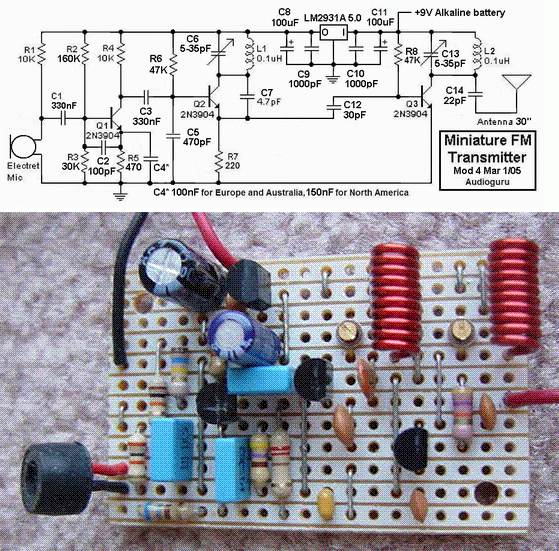
Here is an FM transmitter that looks to be well-designed. Apart from the complex circuit, there are a number of fundamentally incorrect features that make the circuit unreliable.
And the layout is one of the worst I have seen for an FM transmitter.
This type of circuit should NEVER be laid out on strip-board and any type of board that has extra conductive lines as they create "wires" that radiate signal and they can be so effective that all the signal is radiated and none is retained to keep the oscillator in a state of oscillation. That's why this type of layout can result in non-operation.
The first item we will look at is the "Q" of the tank circuit.
This is a factor known as "Quality" and comes from the fact that an inductor will produce a voltage (of opposite polarity) that can be about equal to the voltage applied to it.
And that's what a circuit like this FM transmitter does. The voltage produced by the capacitor and parallel inductor on the collector, will produce a voltage about double the 5v on the rail.
These two components are called a TANK CIRCUIT and to get them to produce a high voltage, the energy stored (and released) by the capacitor must be equal to that of the inductor. The two work like tipping water from one jug to another of the same size and back again. If one jug is smaller, we only get the energy from the smaller jug.
In this case the 5-35p air trimmer will be set at about 20p for 90MHz while the energy stored in the 10 turn coil will be twice that needed. The 10 turn coil should be reduced to 5 turns and the capacitor should be increased to 39p - 47p. This will give the circuit a higher "Q."
With a low Q, the energy through C7 (4p7) will be very small.
We don't know how or where the tracks are cut on the "strip-board" but you can see some of the tracks will connect to the end of the 4p7 that goes to the emitter.
This track acts like a "transmission line" and since it is very wide, it will have a high value of radiation.
This means a certain amount of the energy delivered by the 4p7 will be lost to the surroundings and any handling of the project will cause drifting or it could come to a point where the oscillator fails when handled.
In addition, some of the energy delivered by the 4p7 is being lost via the 30p coupling capacitor and the circuit may fail to work. We found 10p is needed.
The circuit may be successful as the oscillator transistor is being heavily driven via the 220R in the emitter. This may overcome the short-falls in the other design-concepts, but the 30p "take-off" should be connected to the collector of the oscillator stage as it will transfer a lot more energy.
High frequency circuits like this need to be designed so the power rails are "tight." This not only means electrical and electronic "tightness" but also physical tightness.
The 1n across the power rails for the oscillator is insufficient to give good tightness (it should be 22n) and the placement of the components on the board is far too spread-out.
This makes the project very susceptible to handling and drifting.
Since the output transistor is a buffer, the 22p on the antenna is not needed and simply reduces the range.
The 10k resistor for the electret mic is too low for our high-sensitivity microphones. It should be 47k for 5v rail.
The 100u electrolytic across the battery is totally unnecessary as the current consumption is only a few milliamp. In addition, the 100u on the output of the regulator needs to be only 1u to 10u.
Overall, I consider the circuit is taking 2 - 3 times more current than it needs.
Our 9v Voyager circuit consumes 7-10mA for 800metre range. This circuit will consumes more than 25mA.
One final point. The air trimmer should be in parallel with a capacitor (39p) so the trimmer is only adjusting a small amount of the total capacitance. This makes it easier to tune across the band and set the frequency.

Audioguru-FM-Tx.jpg
 
Thanks for the added information, it is a little hard to read being all in one block. But its better than "motor boat".

Colin no one is jealous of your site, I have looked a few times. But lets be real, its extremely outdated. Too many bits flashing and distracting, not the best navigation system on top. It needs bringing into the 21st century if I am honest. I have no idea why you was banned and it isnt my business. I am sure you have a few sore points, but we have all moved on from that rubbish.

Notice how in the last post you actually contribute something useful, that is the way things are now done here. Ego's and showing off gets left at the door, yes sure having a different view point is fine. Some of the best threads are where two people offer details and examples to support there position, things are kept CIVIL. Sometimes agreement isnt reached but nothing wrong with that, the worse cases are where people just go into minute detail in threads where a simple answer is required.

Offering your assessment of the circuits serves a purpose and is useful, I am sure other will have different views on how things should be done. As long as people keep cool and show a bit of respect, then the site dosnt end up looking like a battle ground for a few large ego's.

And dont forget, you may have given links in the past, but if you reply to a post and mention a site, then its just common sense to put a link up to the page with the circuit one. Like I said I wasnt actually having a go, but having been through all that rubbish last time, I wont sit back and watch it start again. Yes we have mods, yes the mods do a good job, but it is also down to the members to speak up, especially when people start going against the ethos and personality of the forum.

Anyway thanks for the more detailed reply.
 
My FM transmitter works perfectly. The stripboard has all of its strips cut to be as short as is possible and so that each strip is used for many tracks of the circuit. The pieces of strips and a few jumpers make a compact pcb.
On an LTspiceIV simulation I tweaked many parts value changes and ended up with a perfect sinewave high level output into a 75 ohm antenna.
My oscillator emitter "transmission line" is only 0.4" long. I copied my coils and trimmer capacitors from the site of Elliot Sound Products who is also Down Under.
On the simulation, the oscillator does not work when its output is at the collector but it works when it is at the emitter.
My 1nF supply bypass capacitor for the oscillator has a reactance of only 1.6 ohms at 100MHz which is low enough.
I used 100μF at the output of the 5V regulator because it is a low dropout type (so that the circuit still works when the battery has dropped to 5.5V) and its datasheet says it must be 100μF to avoid oscillation.
Most electret mics draw about 0.25mA at 2.5V. For 2.5V across it when powered from your 47k resistor the DC voltage must be 2.5V+ (47k x 0.25mA)= 14.25V which is much too high a resistor value and voltage. My 10k is perfect.
My transmitter has a higher battery current because it is much more powerful than Colin's transmitters.
 
Status
Not open for further replies.

Latest threads

New Articles From Microcontroller Tips

Back
Top