Continue to Site

Welcome to our site!

Electro Tech is an online community (with over 170,000 members) who enjoy talking about and building electronic circuits, projects and gadgets. To participate you need to register. Registration is free. Click here to register now.

  • Welcome to our site! Electro Tech is an online community (with over 170,000 members) who enjoy talking about and building electronic circuits, projects and gadgets. To participate you need to register. Registration is free. Click here to register now.

Can you build me a DC motor speed controller?

Status
Not open for further replies.

diy549

New Member
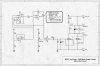
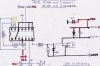
Hello all, I need a speed controller to control the motor speed of my two DC gear motors. I am trying to get a consistent speed under different loads. The motors are 12 volts and 6 amps and they are coupled together. Here is the **broken link removed**

PM me a price and for more details.

Thanks
 
Last edited:
I can't find one. do you have a link. All the ones I have come across are open loop controllers with no speed regulation.
 
You need a speed feedback device (like an encoder). You need one with speed feedback so it can maintain the same speed.

I'm searching for a cheap one. Many of them are around the $100 mark.
 
Last edited:
One idea is to just have a power supply with two different preset output voltages, higher voltage for Up; lower voltage for Down.

Presumably, there is some sort of an Up/Down switch with limit switches to stop the motors at the extremes of travel. Just add a pole to the Up/Down switch so that the power supply knows which voltage to put out.

Now if the two motors have to remain in sync during an Up or Down cycle, that makes this infinitely harder...
 
Last edited:
Now if the two motors have to remain in sync during an Up or Down cycle, that makes this infinitely harder...

Unless he just connects them together mechanically and electrically so they can't be out of sync. I assumed that's what he was doing- one motor on each side of the bed. The bed is the common mechanical connection.

THe voltage way is a good idea and simple since he probably doesn't care if the bed remains at exactly constant speed- he just wants it to not go "too fast" or "too slow". Another take on that is to use a regular motor driver with no feedback, but give it a different duty cycle on the way up and on the way down. Then you only need one battery.

EDIT: Are any of these to your liking?
http://www.robotshop.ca/multiple-motor-controllers-2.html
 
Last edited:
One idea is to just have a power supply with two different preset output voltages, higher voltage for Up; lower voltage for Down.

Presumably, there is some sort of an Up/Down switch with limit switches to stop the motors at the extremes of travel. Just add a pole to the Up/Down switch so that the power supply knows which voltage to put out.

Now if the two motors have to remain in sync during an Up or Down cycle, that makes this infinitely harder...

Thats what I was thinking, just to make things simple. The motors will always be in sync because they are couple together.
 
Thats what I was thinking, just to make things simple. The motors will always be in sync because they are couple together.

So what are you using as a power supply? Voltage? Current? Regulated or not?

If your supply is adjustable, what voltage to you have to set it to for Up vs. Down?
 
So what are you using as a power supply? Voltage? Current? Regulated or not?

If your supply is adjustable, what voltage to you have to set it to for Up vs. Down?

I'm using a 6/12v trickle charger until I decided which power supply to get. I have it set at 6 volts at 10 amps, going UP its just a tad slow and going DOWN its a tad to fast. At 12 volts it moves too fast in both directions. I am going to pick two speed controllers and a couple of limit switches and call it a day.
 
I'm using a 6/12v trickle charger ... I have it set at 6 volts at 10 amps, going UP its just a tad slow and going DOWN its a tad to fast. At 12 volts it moves too fast in both directions. I am going to pick two speed controllers and a couple of limit switches and call it a day.

A battery charger puts out rectified DC with no filtering, so it has a lot of ripple. It also has very poor voltage regulation; in fact it is more a current-source rather than a voltage source. No wonder your motors are not well behaved.

If you can lay your hands on a 5 to 10Ah 6V battery, try that as a temporary power source for the motors. The motors may run much better in both directions.

In any case, you should be looking for a 5 to 7Vdc, adjustable, electronically regulated, 10A power supply. Check the surplus stores. They frequently sell industrial power supplies like that. Most have a screwdriver adjustment over that voltage range.

I found a 5 volt psu that is adjustable up to 5.5 volts and a 9 volt psu that is adjustable down to 7.5 volt, just my luck. Can I use the 9 volt psu with a speed controller to get the speed just right
 
I found a 5 volt psu that is adjustable up to 5.5 volts and a 9 volt psu that is adjustable down to 7.5 volt, just my luck. Can I use the 9 volt psu with a speed controller to get the speed just right
I think that your motors would run well on a regulated 5VDC supply.
 
Dc motor speed control

The best way to control the speed of a dc motor,is to adjust the ampage draw.This is done with a Pulse Width Modulator (PWM) a motor of your specification 12v @ 6amps,should not create any problems.A PWM using 1 mosfet & a LM324N Quad-op-amp,is capable of 15 amps continuous.there are very few other components required.If you decide to build one,just bear this in mind,never ground the drain pin of the Mosfet,never use the PWM without a suitable heat-sink (even for testing)& use a 14 pin socket to mount the Quad-op-amp. here's the diagram,& a rough schematic.good luck.
 

Attachments

  • PWM diagram.jpg
    PWM diagram.jpg
    1.1 MB · Views: 1,392
  • PWM Scematic.jpg
    PWM Scematic.jpg
    2.8 MB · Views: 2,214
Thanks for the diagrams I need something like this myself and stumbled apon this thread.
Ill let you know how it go's for my project which is sort of similar to the original apart from some basics.
 
reversing & speed control

Hi. zorbzz, Thanks for the interest,I've improved the info,so you might find this pdf usefull,any help you need,"just ask" Terry;
 

Attachments

  • polarity reversing & speed control.pdf
    2 MB · Views: 601
Last edited:
Status
Not open for further replies.

Latest threads

New Articles From Microcontroller Tips

Back
Top