Hi all,
I want to use a circuit to dim the lights in my lizard tanks to keep the temperature at a preset level.
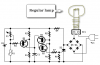
Do you think the link below shows a circuit that could be used as a dimming thermostat upto 250W 240VAC? Also where would I connect the lamp.
Thanks guys.
https://www.redcircuits.com/Fan.GIF
I want to use a circuit to dim the lights in my lizard tanks to keep the temperature at a preset level.
Do you think the link below shows a circuit that could be used as a dimming thermostat upto 250W 240VAC? Also where would I connect the lamp.
Thanks guys.
https://www.redcircuits.com/Fan.GIF
Last edited: