Continue to Site

Welcome to our site!

Electro Tech is an online community (with over 170,000 members) who enjoy talking about and building electronic circuits, projects and gadgets. To participate you need to register. Registration is free. Click here to register now.

  • Welcome to our site! Electro Tech is an online community (with over 170,000 members) who enjoy talking about and building electronic circuits, projects and gadgets. To participate you need to register. Registration is free. Click here to register now.

Can someone please explain this light switch wiring to me?

Status
Not open for further replies.

solaraxis

Member
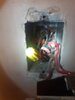
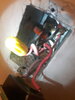
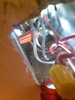
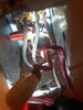
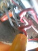
This was likely wired in the 70's here in Canada. I've been studying 3-way circuits, 2-way circuits, general practices and circuit flow for the last 2 hours trying to understand why it's wired this way, because ultimately I'd like to install a dimmer switch that's supposed to have a green connection to ground with what I assume is supposed to connect ala single pole wiring connections. I can't find this wiring in my lightswitch box anywhere online, the closest I've found was a UK one with a loop terminal in the fixture itself.. Any input would be helpful. I'll check things with a multimeter this afternoon once the housemates are active. Thank you for your help.

EDIT;upstairs room on the same breaker as the room below, only one light switch upstairs, one or two below..
lightswitch wiring.png
 

Attachments

  • 20201004_042722.jpg
    20201004_042722.jpg
    1.5 MB · Views: 246
  • 20201004_042751.jpg
    20201004_042751.jpg
    1.8 MB · Views: 252
  • 20201004_043722.jpg
    20201004_043722.jpg
    2 MB · Views: 244
  • 20201004_043711.jpg
    20201004_043711.jpg
    2 MB · Views: 236
  • 20201004_043731.jpg
    20201004_043731.jpg
    1.9 MB · Views: 231
Last edited:
I wrote and added to this thread a diagram in paint of exactly how it's wired. The white wire in the diagram goes straight through whereas in the picture it is capped for some reason, theres no other wires connecting to it under the cap so maybe they intended to wire a different switch to it? theres only two connections in the switch, the ground in the box is grounded at the back
 
matter of fact, the bare ground wire most likey goes through both the in/out in the back of the box, I am mostly unsure because of the housing/insulation, its angled like a coathanger twist and screwed into the back of the box where it most probably continues on the cables warpath..
 
So on further research, it looks like the power coming in is pigtailed into the switches throughput, rather than simply breaking/bridging the hot connection, then wired back through as a separate line from the main connection into the light fixture. the only reason i can come up with for this is that all of the cables that were ran through each boxes, at least on this circuit, are powered via that black cable, and then branched off to the single light fixtures box by box, rather than connecting individual terminals for each room. So by my understanding... that incoming black wire is connected straight into the breaker that allows power to this section of the building and then split and branched for each box it passes through, at least for the light switches... Does that sound right? I don't want to accidentally switch off the circuit, any expertise on this would be very appreciated.
 
Sometimes the White (Neutral) line runs through the gang box containing the switch and sometimes not. New code in the US now requires the neutral to run through the switch box allowing for newer automation smart switches to be installed which may require a neutral. The Black into the gang box is normally the line hot and as you mentioned should eventually tie into the circuit breaker panel feeding the branch circuits. Red wire is commonly used in 120 VAC systems on the switched side of the switch going to lights or other loads, pretty common in the US and Canada. That would be normal switching for 120 VAC in the US and Canada.

It's also not unusual to split the Hot (Black) at the gang box and run it to another location.

Ron
 
I don't see a ground wire in those pictures. The wiring seems to be either quite old and if it did have a ground wire, it may have been cut off (illegally) at some point in time.
Making modifications, including putting in a dimmer, may require it to meet current electrical code. Without a ground wire, I don't see how you can install that dimmer. Remember, if you do wire it in and something happens and starts a fire, your insurance may not cover your house if it was caused by an electrical modification without a permit and inspection, sorry to say...
For the $75 to $150 it would cost to call in an electrician may be worth the expense, basically because you seem to have a electrical box that does not meet current codes (without that ground wire). Even if the electrician says it is ok, and installs it "somehow", you will be off the hook in terms of liability. PS: Some electrical permits in some provinces cost $75 or more, so an electrician may be worth the expense.
Electricians use 3 wire cable to carry power and a switching circuit all in the same cable, instead of running 2 cables (one for power, one for switched circuit). The black is the source, and the red is usually used to feed the switched power back to a light fixture. In the light fixture, the light it connected to the red and the white (neutral). The black is usually just pig tailed together with no connection to the fixture itself. Ground wires are all tied together in every box/junction as well.
 
I uploaded a video, I just wired it up and flipped back the breaker after double checking the OHM resistance on a multi meter on both lives, and checking voltages for safety.. there is functionality but a strobing effect. The lightbgulbs are LED bulbs 60Watts. is it just the bulbs?
EDIT; truly sorry for the awful camerawork..

 
Looking again at the pictures, there seems to be a bare ground wire on the back left side, twisted to another. Not sure how it is connected to the box. Current code (in Ontario) requires one to use a pig tail bare wire to join all bare wires together, with an extra bare wire going to the grounding screw in the box.. Where your question mark is in the sketch is the critical part for a ground wire, it has to come from the "feed" side, and all wires have to be joined together. If no ground wire from the cable on the right, that is where you would need to call an electrician.
PS: The "power feed" and "power to next fixture" may be reversed in my drawing, I don't know which is actually fed from the breaker.
 
so the ground wire goes straight through both sides, with it screwed into the back of the box and twisted off. The left side is the main breaker side, with the hot wire pigtailed through the lightswitch into the light, and god knows where the black goes after that..
 
Watched part of the video. Use a bare wire for the ground (green wire), not red. Strip a regular wire if necessary. You cannot screw ground wire to the box any longer, technically not legal any more (in Ontario at least). You have to use a MAR connector to twist all the bare wires together, with an extra bare wire to the box from that connector.
In the "old" days, everyone would simply connect the bare wires to the box grounding screws, but it was found that occasionally those wires were screwed too tight and broke when someone moved wires around (like putting in a dimmer or replacing the switch). That broke the ground path for fixtures downstream a dangerous situation. Now, all grounds are to be pig tailed together, then the extra bare wire from that pigtail to the box. This way, if a ground breaks on the box screw, it does not affect the ground downstream, all grounds are still tied together, and all other boxes still have a valid ground.
 
Now, all grounds are to be pig tailed together, then the extra bare wire from that pigtail to the box. This way, if a ground breaks on the box screw, it does not affect the ground downstream, all grounds are still tied together, and all other boxes still have a valid ground.
I believe that is how I have it wired. Any idea on why it is strobing?
 
As for the dimmer, is it rated for LED lighting? Some are, some are not. Also, the LED bulb has to be "dimmable", again some are some are not.
Bottom line is you have to have both a LED compatible dimmer, and a LED bulb that is "dimmable"
 
If everything is classified as "dimmable", re-check the wiring of the dimmer, to make sure the source and "load" are the right way around. The load should go to the red wire that is in the cable. The source should be the black/red junction.
 
oh ****... the demonstration had these bulbs sitting right next to similar ones with dimmers wired up at home depot. these are not usable with dimmers. woops.
 
Yikes! What helps is when the white wire (HOT feed) to the switch is colored black with tape.

At home, stuff is usualy wired with power to the ceiling fixture and then you had switch loops from the fixture. Now, as Ron said, you need a neutral at the switch for automation devices.
 
its REALLY strobing. dimmer bulb or not, i dont think im supposed to be hearing the dimmer in the switch box strobing as well, you think? I pretty much did nothing different but add a switch with what I assume is a groud loop/attenuator circuit inside the switch itself/ Same connections otherwise.

Also, i was getting voltage readings, though extremely low, from the ground wire when ALLcircuits were cut from the transformer.
 
Status
Not open for further replies.

Latest threads

New Articles From Microcontroller Tips

Back
Top