Continue to Site

Welcome to our site!

Electro Tech is an online community (with over 170,000 members) who enjoy talking about and building electronic circuits, projects and gadgets. To participate you need to register. Registration is free. Click here to register now.

  • Welcome to our site! Electro Tech is an online community (with over 170,000 members) who enjoy talking about and building electronic circuits, projects and gadgets. To participate you need to register. Registration is free. Click here to register now.

can someone help me figure out this ciruit?

Status
Not open for further replies.

yusim

New Member
hi all
this isnt realy a homework ques. but im trying to undersatnd how this circuit works so i figured this is the best place for this post.

i built myself a heart rate monitor that i found **broken link removed**
i had to add a bandpass filter to get the results that they got on the website
but it works fine.

The Question:
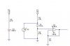
i dont understand what C1 is doing for the circuit and why the circuit doesnt work without it. and why i cant take C1 and R2 out of the circuit in which case the changing resistance of the LDR(R3) would change the potential at the positive input of the opamp thus giving me a pulse for each heart beat?

i hope my ques. was clear any help will be greatly appreciated
thanx in advance,
yusim
 

Attachments

  • hemon.JPG
    hemon.JPG
    11.6 KB · Views: 340
thanks mel8030 for the reply :)

im having some trouble understanding your answer - what do you mean by "The capacitor feeds the change" ?
could you please elaborate

thanks,
yusim
 
R2 biases the input of the opamp at 0VDC. The capacitor couples only the AC signal without changing the DC. The DC at the LDR is affected by ambient light and you do not want the opamp to amplify it.

Your opamp has feedback to provide a voltage gain of 1001 which is too much. The opamp will amplify its own input offset voltage which might cause its output to be saturated.
 
Here goes...

To analyse the circuit, take C1 out of the circuit. R2 clamps the input of the op amp to ground. regardless of how much gain you have around the op amp (in this case 1000), the output of the op amp will be at ground.

the LDR has a voltage going to it from R1. If the LDR has a resistance of 10k, then the junction of R1 and LDR will be at Vcc/2.

If the LED shines through your finger any light coming out of the other side will be picked up by the LDR. The LDR will change its resistance according to the light it picks up (it goes down with increasing light level). As your blood pulses around your finger, the light level picked up by the LDR will change, causing the voltage at junction of LDR and R1 to pulse (sorry!) up and down.

You only want the pulses to be amplified (not the pulses + Vcc/2), so this voltage is capacitively coupled to the input of the op amp using C1. capacitors only pass ac and block dc (in this case they block the Vcc/2 voltage across the LDR).

The op amp then amplifies this (Pulsed) voltage. If you short it out, the Vcc/2 will be applied to the input of the op amp and the output will try to get to vcc/2 * 1000

Hope this helps
 
wow thank you very much audioguru and Electronworks, i now understand completely

audioguru said:
Your opamp has feedback to provide a voltage gain of 1001 which is too much
i actually built this circuit the way i posted it and it works fine - i guess the amount of light that gets through the finger must change only slightly

thanks again for your great replies
yusim
 
Status
Not open for further replies.

Latest threads

New Articles From Microcontroller Tips

Back
Top