Continue to Site

Welcome to our site!

Electro Tech is an online community (with over 170,000 members) who enjoy talking about and building electronic circuits, projects and gadgets. To participate you need to register. Registration is free. Click here to register now.

  • Welcome to our site! Electro Tech is an online community (with over 170,000 members) who enjoy talking about and building electronic circuits, projects and gadgets. To participate you need to register. Registration is free. Click here to register now.

Can I use a diode to lower the voltage of a battery charger output?

Status
Not open for further replies.

DarrenB

Member
I am looking for a simple way to lower the voltage of my 8.4V 7A charger. The charger I am using does not have a trim pot and I do not know which group of resistors control the output voltage. I know that diodes cause a voltage drop. Is it possible to drop between 0.4-0.6V by placing one on the output in series? The DC is constantly connected to the battery when the mains is off would a diode also stop the current draw when it is off?
 
Welcome to ETO.
The 8.4V figure suggests that the charger is specifically intended for charging a 2S lithium battery. Lithium batteries can catch fire or explode if not charged properly. Why do you feel a need to drop the voltage?
If the charger is well designed, switching off the mains would stop current draw via the charger, so any added diode would be superfluous.

Thanks.

I am not really too concerned if it is supposed to charge lithium batteries or not because I simply use it as a power supply to keep my capacitor battery charged up. The problem that I have is that the capacitors discharge too much current when I use them for welding so obviously I need to reduce the voltage. They are currently at 8.4V but I need the voltage to be around 8V. I am using just a regular 2S lithium ion charger which does load the capacitors once the mains is switched off. It doesn't make much difference because I have a li-ion BMS which protects them from over discharging but I would like to know if I can use a diode to drop 0.4V and effectively reduce the fully charged voltage of the capacitors. I know that I could just use a different power supply and buck or boost the voltage but I would like to keep the charger I have as it fits the enclosure.
 
if I can use a diode to drop 0.4V and effectively reduce the fully charged voltage of the capacitors.
Yes, a silicon junction (not Schottky) diode in series should reduce the capacitor charged voltage about 1/2 volt.
Its current rating would need to be at least 10A and would need to be mounted on a heat-sink if the steady current drawn is more than a couple amps.

The simulation below shows a final capacitor voltage of about 7.8V.
The added resistor is to bleed away the small diode forward current at low voltages so it doesn't continue to charge the capacitor.

1671983064527.png
 
Yes, a silicon junction (not Schottky) diode in series should reduce the capacitor charged voltage about 1/2 volt.
Its current rating would need to be at least 10A and would need to be mounted on a heat-sink if the steady current drawn is more than a couple amps.

The simulation below shows a final capacitor voltage of about 7.8V.
The added resistor is to bleed away the small diode forward current at low voltages so it doesn't continue to charge the capacitor.

View attachment 139729
Great. Would you be able to recommend one? Ideally one that is in stock in the UK. Technically is it ok to use some smaller ones in parallel to achieve the current required? It very rarely goes over 3A but when it does it's around 7A for 1-2 min as it charges from 7V back to 8.4V due to the parasitic loses from the charger and BMS.
I noticed that you placed a resistor across the capacitor. Do I use any 1K resistor and connect it to the capacitor 8V positive and negative?
 
Would you be able to recommend one? Ideally one that is in stock in the UK.
No, I'm not that familiar with what's available in the UK, but just look for 10A diodes, any rated voltage.
I noticed that you placed a resistor across the capacitor. Do I use any 1K resistor and connect it to the capacitor 8V positive and negative?
The resistor power dissipation is very low, so any 1k resistor will work.
 
No, I'm not that familiar with what's available in the UK, but just look for 10A diodes, any rated voltage.

The resistor power dissipation is very low, so any 1k resistor will work.
I couldn't find anything with the correct voltage drop. Can I use a Schottky instead?
 
Since the series diode is effectively also an isolator and carries the full charge current, whichever diode type you wind up using, test it to ensure it exhibits no excessive leakage, which in this case is not a good thing. It's a simple preventative measure and quick & easy to do.
 
Would this work for you? I'm sure they are available in the UK. Use one side. Easy to mount on a heat sink, and the price is right. RURH1540C dual 15 amp fast rectifier
What is leakage? :meh: I am sorry but I literally know nothing about electronics. The diode you suggested is ok but I cannot find it in the UK. It needs to be able to withstand 3-4A continuous with 7A peaks and provide a drop of around 0.4V. I am open to any suggestions you might have.
 
Can I use a Schottky instead?
No.
A silicon Schottky has a lower forward voltage drop (which is why they are often used for power rectifiers) which will not be enough for your purposes.
A silicon-carbide Schottky will have too high a forward drop (near 1V).
 
Last edited:
What about a buck converter or a voltage regulator IC?
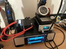
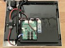
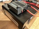
At the moment it all fits into an enclosure and I don't really want to print out all new parts or buy anything else. The charger is fan cooled and the venting fits really well with the aluminium chassis vent so it would be a shame to throw it away. I think all I need to trim off the excess voltage is a diode but it is finding one that is difficult. At the moment it hits the welders limit of 2000A and won't let me pass the calibration.
 

Attachments

  • IMG_0463.JPG
    IMG_0463.JPG
    2 MB · Views: 139
  • IMG_0465.JPG
    IMG_0465.JPG
    2.7 MB · Views: 142
  • IMG_0471.JPG
    IMG_0471.JPG
    2.7 MB · Views: 143
I would suggest your entire premise is wrong? - you don't need to lower the capacitor voltage, you need to lower the current drawn from the capacitors - just use thinner wires from the capacitors to the welder, so it adds a little more resistance.
 
I would suggest your entire premise is wrong? - you don't need to lower the capacitor voltage, you need to lower the current drawn from the capacitors - just use thinner wires from the capacitors to the welder, so it adds a little more resistance.
I am already using a fuse and 8AWG on the output. I couldn't be bothered to change the 6AWG input because it is too short to make enough difference by changing it to 8AWG or even 10AWG. I could also change the voltage cut off on the BMS but this will flag errors all the time. The best way I think is to limit the fully charged voltage to 8V but as the charger does not have a variable resistor trim pot to reduce the voltage I thought it would be easier to use a diode as this was recommended to me for something else that needed voltage to be dropped.
 
No.
A silicon Schottky has a lower forward voltage drop (which is why they are often used for power rectifiers) which will not be enough for your purposes.
A silicon-carbide Schottky will have too high a forward drop (near 1V).
So there isn't any other reason other than the drop being slightly lower than needed? So I could try and see without any problems?
 
Two Schottky diodes in series might give you the required voltage drop?
 
Two Schottky diodes in series might give you the required voltage drop?
Yes, that should work.
LTspice sim below with two 10A silicon Schottky diodes (not silicon carbide) in series:
It reduces the capacitor voltage by about 0.5V (yellow trace).
This voltage can be varied some by changing the value of R2 (lower value will give more drop).

1672852008955.png
 
Two Schottky diodes in series might give you the required voltage drop?
This is exactly what I was thinking but nobody recommended it so I didn't say anything. I know almost nothing about electronics and am reluctant to try anything I am not sure of.

From the tests I did 7.65V is the max to stay below 2kA for calibration and 8V for welding 0.1mm copper strips. 8V yields ~1875A with 0.1mm copper which is the lowest resistance material I use regularly but gives enough room for 0.15mm copper which I might use on the odd occasion. I could end up using the BMS to limit the voltage despite the error counter flags because it actually works really well due to the current not needing to taper as it never reaches the CV region. It acts more like a switch which is nice because it gives me the full charge current the moment the voltage drops below 8V. It is absolutely impossible to weld faster than 8V 7A or 56W so the voltage stays very close to 8V at all times. The upper limit of the capacitors is still respected because the charger can only output 8.4V so even if the BMS failed closed (which as I understand is common for these types of transistors) the capacitors cannot overcharge. Unless of course the balancing circuit somehow went rouge and unbalanced the capacitors and then the main switch transistors failed right after in a closed state.
 
Status
Not open for further replies.

Latest threads

New Articles From Microcontroller Tips

Back
Top