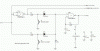
I have a 3 axis (+ relay) stepper driver board with a DB25 interface, as well as pins for manual control.
I can control the motors via MACH3 Mill (demo), using the joystick.
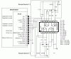
The M Ctrl pins (16) are labeled as follows:
1/2 : +5V
3 : X Axis CLK
4 : :X Axis CW/CCW
5/6 : GND
7 : Y Axis CLK
8 : Y Axis CW/CCW
9 : EN
10 : ESTOP
11 : Z Axis CLK
12 : Z Axis CW/CCW
13 : M/A
14 : GND
15 : Relay CLK
16 : Relay CW/CCW
It appears as though I can't use this board manually, unless it is attached via the DB25 interface.
I presume that this is because the CLK signal is coming from the PC, and/or the CNC software.
This is what I'd hoped to accomplish...
For most of you this will likely be simple, maybe even mundane, but for me, a mechanic, it's a bit more complex.
I want to have a motor, on any axis (I'll be using 2), move to point A, or X inches, when the controller "sees" +5V from a remote device.
When the controller "loses" that +5V, the motor should reverse, and return to "home".
High precision is not required. Part of the problem I think I'm going to have is that the controller board will need to be able to recover
from a loss of power, and still know where "point A" and "home" are, and return to either in the correct direction.
3 manual control buttons may be added as well, once I get closer to understanding what I'm doing. Maybe "Point A", "Home", and "Stop" or even "Reset".
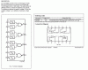
I feel sure that I'll have to "add" a CLK source of some sort to the driver board. Would that be like a 555 timer?
If so, would it be a timer for each axis? Easy enough to add? (I can solder).
My theory...
A> I'll have to add CLK source, probably per axis.
B> I'm sure that this board has no capacity for "memory" of any sort, much less non-volatile. So this will mean no real "logic". Limit switches, at least.
I can do limit switches if I can get my laymans mind around using the M Ctrl inputs, and how to find a "home"
On the other hand, if it's easier, I can salvage the MTD2003 controller ICs from the printer controller board that originally drove the motors, and build something
(even breadboard style) around them to learn what I need to know, then build a PCB.
If any of you can provide a relatively simple schematic, using either the driver boards M Ctrl input, or just the MTD2003 chips. That would be spectacular.
A good laymans example of the use of the M Ctrl input pins would be even better. It appears that these are "standard" stepper controls, and not board specific.
This is my first forray into the realm of steppers, but I learn fast. I already learned that I likely bought the wrong driver board. LOL
Worst case scenario is that I keep a pc attached via DB25, and find software or code better suited for projects, rather than CNC. Ideas?
Anyone have time for this? You rock.
Thanks a lot.
I can control the motors via MACH3 Mill (demo), using the joystick.
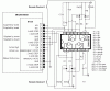
The M Ctrl pins (16) are labeled as follows:
1/2 : +5V
3 : X Axis CLK
4 : :X Axis CW/CCW
5/6 : GND
7 : Y Axis CLK
8 : Y Axis CW/CCW
9 : EN
10 : ESTOP
11 : Z Axis CLK
12 : Z Axis CW/CCW
13 : M/A
14 : GND
15 : Relay CLK
16 : Relay CW/CCW
It appears as though I can't use this board manually, unless it is attached via the DB25 interface.
I presume that this is because the CLK signal is coming from the PC, and/or the CNC software.
This is what I'd hoped to accomplish...
For most of you this will likely be simple, maybe even mundane, but for me, a mechanic, it's a bit more complex.
I want to have a motor, on any axis (I'll be using 2), move to point A, or X inches, when the controller "sees" +5V from a remote device.
When the controller "loses" that +5V, the motor should reverse, and return to "home".
High precision is not required. Part of the problem I think I'm going to have is that the controller board will need to be able to recover
from a loss of power, and still know where "point A" and "home" are, and return to either in the correct direction.
3 manual control buttons may be added as well, once I get closer to understanding what I'm doing. Maybe "Point A", "Home", and "Stop" or even "Reset".
I feel sure that I'll have to "add" a CLK source of some sort to the driver board. Would that be like a 555 timer?
If so, would it be a timer for each axis? Easy enough to add? (I can solder).
My theory...
A> I'll have to add CLK source, probably per axis.
B> I'm sure that this board has no capacity for "memory" of any sort, much less non-volatile. So this will mean no real "logic". Limit switches, at least.
I can do limit switches if I can get my laymans mind around using the M Ctrl inputs, and how to find a "home"
On the other hand, if it's easier, I can salvage the MTD2003 controller ICs from the printer controller board that originally drove the motors, and build something
(even breadboard style) around them to learn what I need to know, then build a PCB.
If any of you can provide a relatively simple schematic, using either the driver boards M Ctrl input, or just the MTD2003 chips. That would be spectacular.
A good laymans example of the use of the M Ctrl input pins would be even better. It appears that these are "standard" stepper controls, and not board specific.
This is my first forray into the realm of steppers, but I learn fast. I already learned that I likely bought the wrong driver board. LOL
Worst case scenario is that I keep a pc attached via DB25, and find software or code better suited for projects, rather than CNC. Ideas?
Anyone have time for this? You rock.
Thanks a lot.