Hello again,
It's another day
")
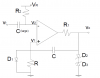
Below we'll call R1 just R because it makes the text easier to read...
Ok, we start with:
V3=(1-e^(-t/RC))*(V1-V2)+V2
solve for t:
t=RC*ln((V2-V1)/(V3-V1))
replace V2 with -Vr:
t=RC*ln((-V1-Vr)/(V3-V1))
inside the ln() multiply top and bottom by -1:
t=RC*ln((V1+Vr)/(V1-V3))
replace V1 with Vs:
t=RC*ln((Vs+Vr)/(Vs-V3))
replace V3 with Vd:
t=RC*ln((Vs+Vr)/(Vs-Vd))
replace R with R1:
t=R1*C*ln((Vs+Vr)/(Vs-Vd))
and we have the required equation.
There's a problem however. The initial cap voltage here is not -Vr it is actually Vd-Vr because just before this period starts the right side is at -Vd and the left side is at -Vr, which means the total voltage across the cap is Vd-Vr. Thus if Vr=3v and Vd=8v, the initial cap voltage is -5v not -3v. Sorry about that.
This means you will have to rework the equations above using this new information.
We will ultimately test all the equations in a circuit simulator in the end too.