Continue to Site

Welcome to our site!

Electro Tech is an online community (with over 170,000 members) who enjoy talking about and building electronic circuits, projects and gadgets. To participate you need to register. Registration is free. Click here to register now.

  • Welcome to our site! Electro Tech is an online community (with over 170,000 members) who enjoy talking about and building electronic circuits, projects and gadgets. To participate you need to register. Registration is free. Click here to register now.

can anyone help me to solve this circuit theory question?? thank you in advance :)

Status
Not open for further replies.
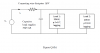
Q: A 60Hz, 120V ac source supplies a group of loads as shown in Figure. If the voltage source is Vs=120V, find the apparent power of the source and the current Is.

capacitor is connected parallel with load 1 and also parallel with load 2.
connecting wire dissipates 1kW.
load 1: 50kW with pf=0.7 lagging
load 2: 20kW with pf=0.8 lagging
capacitor: 30kVAR
 

Attachments

  • Capture ect.PNG
    Capture ect.PNG
    37.5 KB · Views: 307
Last edited:
This is how I would do it (although it has been 20 years since I last did electrics). Each load is made up of a resistance in series with an inductance. For the first load, it dissipates 50kW, which is resistive. You can work out the resistive element of each load by doing 50kW/120 (=416A), giving a resistance of 288m Ohms. Your power factor is 0.7, so you have the hypotenuse at 1 and the x axis at 0.7, so you need an inductance on the y axis that gives an angle of (cos^-1 of 0.7) (45.57 degrees) at 60 Hz (294 mOhms which is 779uH), so you have worked out the elements of the first load. Repeat this for the second load.

Work out the parallel combination of the 2 loads plus the capacitor. This 'lumped' load then forms a series network with the pure resistance that makes up the wire loss. You can then work out the current that flows through this and its phase with the input voltage.

I need to check the actual figs above, but that is the method I would use.

Others please discuss... and tell me where I have gone wrong...
 
Last edited:
Hmm. I think I have the power factor bit incorrect.. Let me think... and get back to you... - I've just corrected it. I think
 
Last edited:
hi there, i really2 appreciate for ur answer. I already, attached the circuit picture in my post. can refer to it :)
hi,
Please post what you have calculated for the answer to that homework question, members do not usually supply the full answers only hints and tips.
 
but the problem is i dont know how to apply the power disipate by the wire n also how to find the total power factor of whole circuits. please give me some hints
 
power desipiated by the wire can be taken in sereis with all other 3 elements
Industrial facilities tend to have a "lagging power factor", where the current lags the voltage (like an inductor). This is primarily the result of having a lot of electric induction motors - the windings of motors act as inductors as seen by the power supply. Capacitors have the opposite effect and can compensate for the inductive motor windings. Some industrial sites will have large banks of capacitors strictly for the purpose of correcting the power factor back toward one to save on utility company charges. that is what your circuit is all about.
Industrial facilities tend to have a "lagging power factor", where the current lags the voltage (like an inductor). This is primarily the result of having a lot of electric induction motors - the windings of motors act as inductors as seen by the power supply. Capacitors have the opposite effect and can compensate for the inductive motor windings. Some industrial sites will have large banks of capacitors strictly for the purpose of correcting the power factor back toward one to save on utility company charges. a power factor of 0.7 means there is 70% of power coming as true power from apparent power.
 
This is how I would do it (although it has been 20 years since I last did electrics). Each load is made up of a resistance in series with an inductance. For the first load, it dissipates 50kW, which is resistive. You can work out the resistive element of each load by doing 50kW/120 (=416A), giving a resistance of 288m Ohms. Your power factor is 0.7, so you have the hypotenuse at 1 and the x axis at 0.7, so you need an inductance on the y axis that gives an angle of (cos^-1 of 0.7) (45.57 degrees) at 60 Hz (294 mOhms which is 779uH), so you have worked out the elements of the first load. Repeat this for the second load.

Work out the parallel combination of the 2 loads plus the capacitor. This 'lumped' load then forms a series network with the pure resistance that makes up the wire loss. You can then work out the current that flows through this and its phase with the input voltage.

I need to check the actual figs above, but that is the method I would use.

Others please discuss... and tell me where I have gone wrong...

where did 294 mOhms comes from. and how to find the apparent power of the source by using this?
 
Power Factor is Real Power/Apparent Power. Real Power is on the x axis. Apparent power is the Hypotenuse. Inductance represents an impedance UP the y axis, Capacitance represents an impedance DOWN the 7 axis (ie negative). Resistance is on the x axis (and only on the x axis). So as neptune says, you can use a capacitor to reduce the effect of inductance (and get a zero shift on the y axis - ie power factor of 1). See also: Argand diagram. That is all I am going to tell you as you should have enough reading material from your course work to work out the rest...
 
i mean, wat is de mean of this sentence "Work out the parallel combination of the 2 loads plus the capacitor. This 'lumped' load then forms a series network with the pure resistance that makes up the wire loss. You can then work out the current that flows through this and its phase with the input voltage."?

is it mean,find the combination of power of the 2loads n capacitor? i thought power of capacitor minus with both loads?
 
Each load (50KW and 20kW) can be represented as a series inductor and resistor, so you have a resistor in series with an inductor and another resistor in series with an inductor. These 2 networks are in parallel. This is also in parallel with a capacitor. You need to do a network analysis to see what this network looks like. This is your lumped load. This can be then treated as the bottom element in a potential divider, with the top element being the resistor making up your 1kW loss. Go from there...
 
way to go

Hi.

I cannot imagine this is so hard to get.

This is the way to go:
  1. Convert all loads to its corresponding complex number (remember to include wire loss here)
  2. Get the sum of the complex numbers
  3. Now you have the total power consumption from all loads together.
  4. You already have voltage, so current shouldn't be hard to find now.
 
Hi,

The trouble she (i assume cinderella refers to a female poster) is probably having is how to relate everything together to get to the solution, as none of the load values are given just the power or VA's.

Cinderella, perhaps you can explain just exactly what you are not able to figure out, and how you are attempting it in the first place.
 
Cinderella, perhaps you can explain just exactly what you are not able to figure out, and how you are attempting it in the first place.
She have already told:

but the problem is i dont know how to apply the power disipate by the wire n also how to find the total power factor of whole circuits. please give me some hints
And if she follows my steps, she should find an apropriate solution.

It's important to treat any effects as complex numbers to get this done. Doesn't even have to think about voltage and amps.
 
Last edited:
Hi again,

Grossel:
Ok, show her how to convert the first inductive load to a complex number. Use a different value for the power so she doesnt get the answer directly :)

Here's another hint cindy:
The total true power is equal to the sum of the individual true powers.
 
Ok, fair enough. I'm sorry If complex number is out of the question in tems of solving this.

Anyway:
Say you have inductive load as 20kV and pf = 80 (realistic). So make this into a complex number with a magnitude (kVA) and angle (degrees), follow these steps:
  1. Calculate the angle. This will be a result of ARCSIN(0.8)
  2. Put the angle together with the magnitude. The complex number would be writed as (20;53) (I doesn't find angle and degrees sympls here).

Two tip:
  1. Make a simple simple draft and put the numbers on a coordinate system to check that it's ok.
  2. Complex numbers is very similar to vectors (when origo is starting point). That is - doing mathematical operations on complex numbers is just the same as for vectors. Only difference is that vectors is represented as a arrow that might have a starting point on a different location than origo, while a complex number is a point that is always measured according to origo.
  3. If you're not familiar with complex numbers, read here - this guide.

[edit]
I add some pictures I made using Geogebra. Be aware that when I upload graphics on this forum, I have absolutely no control over their order. Look at the pictures file name.

[edit2]
It seems that the images is automatically ordered by file name. Good to know for the future.
 

Attachments

  • explanation2-1.png
    explanation2-1.png
    27.7 KB · Views: 290
  • explanation2-2.png
    explanation2-2.png
    20.5 KB · Views: 290
  • explanation2-3.png
    explanation2-3.png
    23.3 KB · Views: 294
  • explanation2-4.png
    explanation2-4.png
    29.7 KB · Views: 301
  • explanation2-5b.png
    explanation2-5b.png
    27.4 KB · Views: 290
Last edited:
Status
Not open for further replies.

Latest threads

New Articles From Microcontroller Tips

Back
Top