Continue to Site

Welcome to our site!

Electro Tech is an online community (with over 170,000 members) who enjoy talking about and building electronic circuits, projects and gadgets. To participate you need to register. Registration is free. Click here to register now.

  • Welcome to our site! Electro Tech is an online community (with over 170,000 members) who enjoy talking about and building electronic circuits, projects and gadgets. To participate you need to register. Registration is free. Click here to register now.

Can anyone help me about RF sensor switch used relay circuit ??

Status
Not open for further replies.

ken2000

New Member
Can anyone help me about RF sensor switch used relay circuit ??

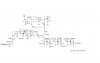
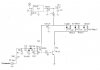
I do not sure this will working or not ? pls check on the photo..
This i will use RF power 1W input for drive transistor 2N3904 and switch TIP29 .. for 3 relay ( 3 coils 178 ohm/coil ) I do not sure if used 2 x 2N3904 it will work or not ? and if use TIP29 like this photo will work ?? can anyone advice me ? pls.. The relay is 5VDC coil 178 ohm...

Thanks..
 

Attachments

  • relay_circuit.JPG
    relay_circuit.JPG
    40.2 KB · Views: 661
It will probably work a lot better like this.

JimB
 

Attachments

  • relay_circuit_modified.JPG
    relay_circuit_modified.JPG
    49.5 KB · Views: 980
The OP's circuit may actually work. He mentions driving it with 1 W of RF power. With this much input he might have a peak RF voltage of roughly 7 volts before the detector. The diodes are arranged to double the voltage and the load on the detector is only about 30 to 50 microamps, so I guesstimate that the voltage that gets into the 3904 base will likely be enough to drive this follower arrangement, given enough gain from the two transistors. Assuming gain of 50, that 50 microamps would turn into 125 mA, which means the output transistor will saturate with its 83 mA load. So it might work.
 
RF sensor relay switch

It will probably work a lot better like this.

JimB

Thanks you very much JimB..

I will test it... Oh if i not used TIP 92 ( TR2 ) , but will used 2N3904 for ( TR2 ) it will work ?? I dont know about bias on TR2 if used 2N3904 and it will can carry switch 3 relay ??

This supply 5V will come from 12-13.8V regulator 12-15A into this IC1 regulate 5V ( this you think it will not damage the IC1 ??) and after out from IC1 it have 5V this +5V will not damaged the relay ?? because relay coil only 178 ohm.. ( i will used RF relay HF3S AXICOM Relay )
- This relay spec 5 Vdc , Coil power 140mW , Coil resistance 178Ω :

Number of contacts and type 1 changeover (SPDT)
Contact material Silver, gold-covered
Limiting continuous current at max. ambient temperature 2 A
Maximum switching current 2 A
Maximum swichting voltage 220 Vdc / 250 Vac
Maximum switching capacity 60 W / 62.5 VA / 50 W (2.5 GHz)
Initial contact resistance at 10 mA / 20 mV < 100 mΩ
Mechanical endurance 107 operations
Max. Continuous RF-power 100 W @ 3 GHz (with appropriate cooling, only)
150 W @ 2 GHz (with appropriate cooling, only)
Peak RF-power 300 W (with appropriate cooling, only)


Thanks
 
Status
Not open for further replies.

Latest threads

New Articles From Microcontroller Tips

Back
Top