killivolt
Well-Known Member
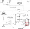
Is it possible to do this with a 5vdc supply instead of 12vdc. Of course with different values.
I'm trying to use a port pin that has about 400ma to drive the circuit. I want to switch a DPDT relay momentarily with the 1 second hold time.
This is the circuit in question from another post. (Thanks goes to KMoffet)
"If I answer this Question I will be able to draw my diagram I want to review"
Thanks again, kv")
I'm trying to use a port pin that has about 400ma to drive the circuit. I want to switch a DPDT relay momentarily with the 1 second hold time.
This is the circuit in question from another post. (Thanks goes to KMoffet)
"If I answer this Question I will be able to draw my diagram I want to review"
Thanks again, kv

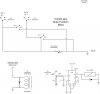
") It looks easier and has the veroboard Layout too!
It looks easier and has the veroboard Layout too!