Mr.K
If you would post what your trying to do here and stop Pm me. I'll do my best to help
you with it. Now
1. If you want to make a dimmer post the circuit or a link to it
2. If your dimmer is to use something like a sony remote you can use the 12F675
3. If it is to have a key pad then you need a bigger chip because of the key pad now you can use a 16f628a lot's of code that you can look at a learn by. Me my self I would use a 18f1230 I like basic and Assembly don't do much in C the 18F you can use swordfish basic
4. If you want help the form is where it at now I -know you think people are not willing to help that's not so they wouldn't be on here.
Post your code or a link to it here something like this
Code:
 LIST p=16F628
 include "P16F628.inc"
 ERRORLEVEL 0, -302 ;suppress bank selection messages
 __config 0x3D18

  cblock 0x20   ;start of general purpose registers
   count   ;used in looping routines
   count1   ;used in delay routine
   counta   ;used in delay routine
   countb   ;used in delay routine
   tmp1   ;temporary storage
   tmp2
   key   ;which key was pressed
   rows   ;counter for number of rows
   code1   ;registers for secret code
   code2
   code3
   code4
   key1   ;registers for keyed attempts
   key2
   key3
   key4
  endc
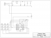
Now down load the circuit for the keypad add your pic and dimmer control to it and let's get started pick'n
 like I mentioned in the pm, I want to make a modification to this hobby project