Continue to Site

Welcome to our site!

Electro Tech is an online community (with over 170,000 members) who enjoy talking about and building electronic circuits, projects and gadgets. To participate you need to register. Registration is free. Click here to register now.

  • Welcome to our site! Electro Tech is an online community (with over 170,000 members) who enjoy talking about and building electronic circuits, projects and gadgets. To participate you need to register. Registration is free. Click here to register now.

caller ID

Status
Not open for further replies.

gaurang_r24

New Member
hello
i urgently need information on how this circuit works mainly the telephone receiver section
please if anyone could help me.
 

Attachments

  • caller.gif
    caller.gif
    18.7 KB · Views: 1,709
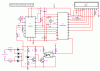
The diodes rectify the line voltage, meaning that you can't get the phone line wires back-to-front.

The transistors and optocoupler form an off-hook detector -- when the line voltage drops below the vicinity of 15V, the leftmost transistor turns off, allowing the transistor driving the optocoupler to conduct. The opto coupler then passes the signal to the microcontroller. There might even be breakthrough when the phone rings due to the high ring voltage being above the BC547 blocking voltage.

The MT8870 is a DTMF receiver/decoder. It is fed audio from the phone line and if a valid DTMF tone is detected, it passes the decoded key number to the microcontroller.
 
AFAIK The caller ID is usually transmitted between 1st and second ring and sent by FSK, not DTMF - MT88E39 or MT88E43 would be appropriate IC for that. But perhaps the circuit is not designed for *incoming* (caller) ID but outgoing (callee ID) or to monitor DTMF dialed during the connected call.
 
Phone systems in 3rd-world countries (plus Finland) use DTMF for caller ID signals.
Modern countries use FSK.
 
Status
Not open for further replies.

Latest threads

New Articles From Microcontroller Tips

Back
Top