Electro Tech is an online community (with over 170,000 members) who enjoy talking about and building electronic circuits, projects and gadgets. To participate you need to register. Registration is free. Click here to register now.
Welcome to our site! Electro Tech is an online community (with over 170,000 members) who enjoy talking about and building electronic circuits, projects and gadgets. To participate you need to register. Registration is free. Click here to register now.
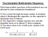
Anyone having a formula to calculate the frequency of the astabil multivibrator in picture? (approximately or preferably exact). Easy to build but analysis is not so straight forward I have discovered.
You must be careful not to use a supply voltage higher than about 5V to 7V for that simple multivibrator. Each coupling cap charges to the supply voltage minus a b-e drop. When a transistor conducts then the charged cap drives the base of the other transistor to a negative voltage almost as much as the capacitor was charged.
Silicon transistors have an absolute max reverse voltage rating for Vb-e of only 5V to 7V because the junction has avalanche breakdown like a zener diode.
Since the junction conducts when you don't want it to, it messes-up calculations for frequency.
Adding a forward-biased diode in series with each emitter to ground fixes it. :lol:
This circuit behaves like an constant current generator charging the capacitors lineary. The slope of charge is determinated by the values and it is easy to make a good calculation for different values on components (Ra and C) based on a plot of the slope (dV/dt) from a oscilloscope. It's more tricky to calculate a universal formula including both Ra and Rb and C together. Naturally there is a limit for resistor values and supply voltage not to damage the transistor.
This circuit behaves like an constant current generator charging the capacitors linearly. The slope of charge is determinated by the values and it is easy to make a good calculation for different values on components (Ra and C) based on a plot of the slope (dV/dt) from a oscilloscope. It's more tricky to calculate a universal formula including both Ra and Rb and C together.
I disagree. The caps charge exponentially by Rb, like any RC circiut. They are discharged with nearly double their voltage across Ra so the curve is a little straighter. It is easy to calculate the charge/discharge times and frequency if the transistor bases aren't allowed to breakdown.
Anyone having a formula to calculate the frequency of the astabil multivibrator in picture? (approximately or preferably exact). Easy to build but analysis is not so straight forward I have discovered.
Try RA * C * 2, if both RA's are the same and both Capacitors are equal. This will make the equation for the time it takes the output to go on and off.
In some cases, you will need to multiply the answer by 1/(2* pi). I forget when this happens, but in your case, I dont think it needs to be applied.
MStechca,
The charged capacitor is driven negative nearly the supply voltage. So it discharges into Ra with about double the expected current.
The capacitor's voltage reaches zero and it begins being charged in reverse by Ra when the transistor turns on in about 0.7 RC time constants. That is for a half cycle, double the time for a full cycle.
The polarity of voltage across the timing capacitor reversed during operation. For long timing delay which requires the use of an electrolytic capacitor, the + lead of the capacitor is connected to the collector. If a very high value resistor is used for the timing purpose, it might not be able to charge up the capacitor during voltage reversal. The leakage current through the capacitor when a reversed voltage is applied might be higher than the charging current so the circuit won't work.
Hi Eblc,
The cap's voltage reverses a base-emitter voltage drop of only 0.6V, and only for a moment, so I don't think an electrolytic cap would leak any current in a two transistor multivibrator. :lol:
I've just tested a 47uF 50V capacitor at 0.65V reversed voltage.
You're right Audio, they don't show any leakage current even on my 50uA multimeter.
I have the impression that electrolytic capacitors leak because the pointer always not return to infinity if I measure a cap using resistance range Rx1K with my meter leads reversed. So they do leak when the voltage is about 3V but unmeasureable on my multimeter at 0.65V.
This site uses cookies to help personalise content, tailor your experience and to keep you logged in if you register.
By continuing to use this site, you are consenting to our use of cookies.