Continue to Site

Welcome to our site!

Electro Tech is an online community (with over 170,000 members) who enjoy talking about and building electronic circuits, projects and gadgets. To participate you need to register. Registration is free. Click here to register now.

  • Welcome to our site! Electro Tech is an online community (with over 170,000 members) who enjoy talking about and building electronic circuits, projects and gadgets. To participate you need to register. Registration is free. Click here to register now.

C/E frequency range

throbscottle

Well-Known Member
I've been playing with a 1 transistor amplifier in LTSpice. Trying to get a flat response from DC to some high frequency. Why is it that whatever I do, the response starts to roll off around 20 - 30MHz? I've put in a BFR181, specced for broadband use, but still starts to roll off at the same point. Trying to push it further with capacitors and/or inductors produces a hump at the high end with little improvement in bandwidth.

I also tried straight and folded cascode versions. It's a bit better, but the change in response still happens in approximately the same place. Only the degree of change is different. Same with trying different transistors. They roll off different amounts, but it's around the same place.

What's the secret?
 
Post your .asc file.
 
I've been playing with a 1 transistor amplifier in LTSpice. Trying to get a flat response from DC to some high frequency. Why is it that whatever I do, the response starts to roll off around 20 - 30MHz? I've put in a BFR181, specced for broadband use, but still starts to roll off at the same point. Trying to push it further with capacitors and/or inductors produces a hump at the high end with little improvement in bandwidth.

I also tried straight and folded cascode versions. It's a bit better, but the change in response still happens in approximately the same place. Only the degree of change is different. Same with trying different transistors. They roll off different amounts, but it's around the same place.

What's the secret?
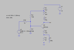
All transistors run out of gain at high frequency unless they are special purpose RF transistors that have been fabricated and characterized to work at high frequencies. There are also parasitic components that are introduced by different method of circuit construction.
 
One .asc file coming up...

Papabravo - the BFR181 is just such a transistor as you describe. I know about parasitics but this is a simulation anyway... What I'm trying to establish is why, for a variety of RF and non-RF transistors, the rolloff starts in around the same place (give or take 10MHz or so) and what I should be doing to get around it!

DeepinScreenshot_select-area_20230331125509.png
 

Attachments

  • amp.asc
    1.6 KB · Views: 104
The logical answer is that the passive components affect the response at high frequencies.
 
I can't argue with the logical answer. What you say is unequivocally true. But what I really want is, the helpful answer :)
 
A possibly more helpful answer is that your CE amplifier "appears" to be class A. In a class A amplifier, the active device is always conducting. Most RF amplifiers are Class C where the active device is seldom conducting. They are AC coupled and have tuned circuits. The resistors are definitely getting in the way at higher frequencies.
 
Ahhh, that is useful, thank you.
So, suppose I want to keep it class A because I want a nice signal for test purposes, and I want it as flat as I can get it all the way down to DC. So tuned circuits are out and class c is out.
Is the only solution to use increasingly exotic transistors, or is there another configuration I need to be looking at - re-visit the cascode perhaps?
I should try this with an FET.
 
A possibly more helpful answer is that your CE amplifier "appears" to be class A. In a class A amplifier, the active device is always conducting. Most RF amplifiers are Class C where the active device is seldom conducting. They are AC coupled and have tuned circuits. The resistors are definitely getting in the way at higher frequencies.

You're rather missing the point - class-C is used for non-linear (FM, AM - with high level modulation) transmitters, but for receivers, preamps, or linear amplifiers you can't use class-C (just as you can't for audio).

The circuit in question here appears to be a preamp, with a fairly strange configuration? - there are countless single transistor wideband preamps, going back to the 60's (if not the 50's?).

The problem here might be that he's trying to get response down to DC (why?) - usually RF preamps are just that, and often don't start until approaching VHF.
 
Hmm, that's interesting. I get a better response (in simulation) with the quite pedestrian J113 jfet.
 
You've hit the nail on the head Nigel. If I ignore the low end of the spectrum I can get a lovely response!
The strange configuration is just me playing around to find what works.
 
Huh. Changing the peaking coil to a T coil and lowering the base bias resistance did the trick.
New .asc
 

Attachments

  • amp.asc
    1.7 KB · Views: 105
  • DeepinScreenshot_select-area_20230401001134.png
    DeepinScreenshot_select-area_20230401001134.png
    19.3 KB · Views: 122

Latest threads

New Articles From Microcontroller Tips

Back
Top