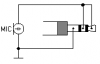
Maybe your electret mic is a 3-wires one instead of a 2-wires one.dear audio guru,
I have made this circuit as per schematics with TL071 and ur modifications, completed last night. Circuit seems working ok as pre amp but it is not sensitive as i have to eat mic to get sound from my amplifier.
Maybe your electret mic is connected upside-down. Its metal case and the pin connected to it is supposed to connect to 0V.
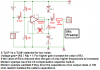
I don't know which circuit you made. My mic preamp circuit that I attach here again has a voltage gain of 101 which is fairly sensitive. My instructions say to inrease the value of R3 for more gain.
Here is what another member said about my mic preamp circuit:
"I tried the setup with out your mods - thanks guru - and the results were astonishing to say the least.
I stood back about 20 feet and spoke with a normal voice. The sound recorder picked it up as if i was standing right next to it..
With your modifications the circuit is more then I had expected! Unbelievable.
By the way, if it isnt too much to ask, what is the gain set at with the 100K resistor?"
")