Continue to Site

Welcome to our site!

Electro Tech is an online community (with over 170,000 members) who enjoy talking about and building electronic circuits, projects and gadgets. To participate you need to register. Registration is free. Click here to register now.

  • Welcome to our site! Electro Tech is an online community (with over 170,000 members) who enjoy talking about and building electronic circuits, projects and gadgets. To participate you need to register. Registration is free. Click here to register now.

Building a traffic light pattern and Im stuck (triac help!)

Status
Not open for further replies.

oxygen454

New Member
Hey guys,

I have this posted in the normal chat as well but just seeing if anyone else can help me out there. More help is always better. I have a traic problem. I am currently testing a MAC15A6 triac which notes on the triac are at...
http://www.onsemi.com/site/products/summary/0,4450,MAC15A6,00.html
I believe the pinouts on 1 and 2 are AC and 3 is trigger. I am testing the triac with 9vdc and 12vdc and it dosent seem to work. Maybe it is because Im not running the one half on 110vdc?

Also if Pin 2 is the same as the thermal backing plate and is connected, does this mean the backing plate is live with what ever pin 2 is carrying which in this case will be 110vac? :?

and lastely ...

If 9 volts has something to do with it and have to go up to 12 volts for thte trigger, then I am wondering if I have to change all my resistors too?

More on this topic is at:
https://www.electro-tech-online.com/threads/multiplex-circuit-question.4306/

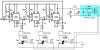
Here is my website with all my diagrams and everything!
http://www.members.shaw.ca/thegarage2/TrafficLight.html


HELP! haha
Chris
 
Okay got enough guts to try the real deal with 110vac and 12vdc. I used a inline fuse and a long extenstion cord incase I had to yank it out of the wall hahaha.

The triac only turned on for a split second when I triggered it but it would not stay on. Something is not right? Not sure what to do, might eventually give up and use relays but they are noisy but will work.
 
I strongly recommend to use an optotriac for TRIAC driving and proper galvanic isolation from mains voltage. With 9VDC You can test the device: push the button, and the bulb lite, and switch off when the 9V removed.Try again with reverse polarity, it will also work. (Thyristor work only one direction.)
 

Attachments

  • TRIACtest.GIF
    TRIACtest.GIF
    1.7 KB · Views: 789
  • TRIACdriver.GIF
    TRIACdriver.GIF
    2.4 KB · Views: 833
Thankyou for your help Sebi! I will give that a try, just still wondering it that means that the thermal backing on the traic is loaded with 110vdc because it seems to be linked with the 2nd terminal. How does a optotriac work?

Chris
 
Yes, most of case the the TO220 metal tab cnnected to pin 2 (transistor: collector, TRIAC: MT2), some types isolated.
The optotriac is a trigger device for triacs. The input LED activate the circuit inside only by light. Most of case the circuit contain zero-cross detector, and between the output pins working a small triac.
 
haha okay I understood some of the that the rest is greek lol not that advanced in the electronics terms yet haha thanks again tho! :)


One other question, if I try this with relays, it seems like the relays work best with 12vdc, so does this mean I have to change my resistors or the curcuit to work with this? I know the 555 will handel up to 15vdc but is that across all the pins?
 
No step back to relay, triac is pretty solution....
 

Attachments

  • Trafic.JPG
    Trafic.JPG
    46.4 KB · Views: 820
Hey sweet thanks for that diagram, that makes a lot more sence now! Thanks man. Will have to give that a try! Dude you are awesome haha

would you know tho if I ran 12 volts through the 555 part of the circuit, if I have to change the resistors even tho its rated for 115 volts? Not sure if all the pins can recieve 15volts. Something I have played with.

Thanks again!
 
Im learning all kinds of stuff from this project I never learned in highschool. I am using a multi power supply that you can plug anything into. Its rated 500mA and goes from 3 to 12 vdc. The weird thing is when I turned it on 12 volts the volt meter said it was 18 volts and cooked my 555 chip whats going on? The chip didnt heat up it just stopped working. So I set it at 6 volts and it come out at 9 volts which I want and works fine. Weird.
 
See the upgraded scheme. The simlpy wallwart supply output voltage true only when full-loaded. Most of electronic circuits no enough the simple capacitor in supply. Apply a regulator chip to supply out (7809 or 7812)

I recommend to try first the cicuit only with LED-s on outputs
 
Thanks a million, the light works just as I wanted it to! I used replays instead of the mosfets and the triacs which worked well and also a multi setting and multi adapting power supply that you can buy for things like walkmans which worked well.

Only thing left is to figure out what kind of variable resistor I can use for the timing. Im not sure how to figure this out or what to use. But thanks again and finishing notes on this will really help! Thanks again!
 
Status
Not open for further replies.

Latest threads

New Articles From Microcontroller Tips

Back
Top