Continue to Site

Welcome to our site!

Electro Tech is an online community (with over 170,000 members) who enjoy talking about and building electronic circuits, projects and gadgets. To participate you need to register. Registration is free. Click here to register now.

  • Welcome to our site! Electro Tech is an online community (with over 170,000 members) who enjoy talking about and building electronic circuits, projects and gadgets. To participate you need to register. Registration is free. Click here to register now.

Building a Power Supply

Status
Not open for further replies.
Please see my edits to your PSU circuit.
As already mentioned, the switch is not doing you any favours. In fact it restricts the versatility of the PSU.
What if you want +12v and +5v at the same time?
Or +12v and -5v at the same time?

You may also want larger capacitors, I will have a think and a calculate later on if someone else does not beat me to it.

JimB

Musics PSU.JPG
 
Hi Jim & Ron

The schematic for the 0 - 30v kit is on the end of the attached. I can't separate it for you unfortunately as I only have PDF reader.
It was my intention that the grounds for the kit and the discretes would be separate with the option to link with a plate on the bananas if needed. someone suggested that a while ago but I can't remember who.

OK Jim I understand the edits, I put the switch in to alternate between the 5v & 12v system but if there is no problem they can be permanently on.

Thanks for all this Guys

S
 

Attachments

  • 0-30v Power Supply.pdf
    202.6 KB · Views: 5,178
Hi Jim

You may also want larger capacitors, I will have a think and a calculate later on

Is this load x C / ripple freq ?

I tried to read that out but I couldn't get my head round it properly so I cheated - I looked at other PSU schematics to see what they had used !!
Is there somewhere you'd recommend to read up on or better still - is there a good reference book about the theory and mathematics. I've seen a number of calculation formulae on here and elsewhere that look very testicle but make no sense to me but I guess they need to.

S
 
ronsimpson wrote:
JimB. Do you think the 9V transformer will work or does he need a 12V transformer?
A 9v transformer would be fine for a 5v supply, but not good enough for a 12v supply.

9 x 1.4 = 12.6v
Allowing for ONE diode drop (we are considering a biphase rectifier here rather than a full wave bridge), that would leave 11.9 volts.
Just plain not enough for a 7812 regulator.

Musicmanager wrote:
Is this load x C / ripple freq ?
Approaching the calculation from both ends.
Assuming:
a 15-0-15v transformer,
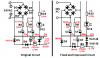
biphase rectification with silicon diodes,
a 7812 voltage regulator.

Rectifying to 15 volts, we will have a maximum DC voltage of (15 - 0.7) x 1.414 = 20.2 volts.
This voltage can only go downwards from there due to:
IxR losses in the transformer, wiring and diodes
Ripple due to discharging the reservoir capacitor.

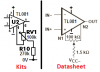
Now consider the 7812.
The Fairchild datasheet gives a dropout voltage of 2 volts, so we need a minimum of 14 volts at the input of the 7812.

To find the capacitor we need:
The maximum voltage is 20.2, the minimum is 14v, so we have a maximum ripple of 20.2 - 14 = 6.2 volts.
One of the accepted formulae for calulating the required capacitance is:

C = (IL x t)/Vripp
Where:
C is the capacitance in Farads
IL is the load current in Amps
t is the period of the ripple in seconds. (for a full wave rectifier with a 50hz supply t = 10ms, for a 60hz supply t = 8.33ms.
Vripp is ripple voltage.

Using our values:
C = (1 x 0.01)/6.2 = 0.0016 F = 1600uF

So , 1600uF is the very MINIMUM capacitance for this thing to work correctly.
The next highest common value is 2200uF, this could be a but marginal, allowing for wide tolerances in electrolytic capacitor values, and loss of value with age.
A 4700uF capacitor would be my choice to give a robust reliable power supply.
The ripple voltage at the reservoir capacitor will be about 2.1 volts, giving us 6.2 - 2.1 = 4.1 volts "headroom" for unknowns and "Ooooh, I never thought of that" items.

JimB
 
The 30V/3A kit is a Chinese copy of an old kit from Greece. The kit from Greece had many parts overloaded such as the transformer, the opamps, the driver and output transistors and many resistors.
We laughed about it at Electronics Lab where the Greek owner posted it as a project, built it and it did not produce 30V at 3A then it blew up.

For example, the TL081 opamps have a maximum allowed total supply of 36V. The 24V transformer will produce 25VAC or more when its load is less than 3A or if it has no load. Then its peak is at least 35.4V and the rectifier bridge with not much load drops it to at least 34V which feeds the positive power terminal of the opamps. The circuit also has a negative supply that is -5.6V which feeds the negative terminal of the opamps. Then the opamps have a total supply of at least 39.6V (could be higher) which is more than allowed.

I calculated the voltage losses which explained why it could not produce 30V at 3A. So we increased the transformer to 28V and more power, replaced the opamps with TLE2141 (44V supply rating) that do not need a negative supply as much as -5.6V (we used -1.3V) and used two 2N3055 power transistors at the output to share the heat. It works well and is reliable.
 
Morning JimB

Thanks for all that work last night, seeing it done before your eyes makes it a hell of a lot clearer than all the reading there is !
I was getting to grips with it last night when I read Audiogurus' critique of the 0 - 30 kit which totally ***** me off, so I gave up on it and went to bed.

I'm hoping you missed the revised schematic when I admitted making a mistake with the transformer
Thanks for that. Eureka I understand it too !
I've realised I'm the architect of my own confusion because what I'm talking about is not what I've drawn !! I'm a complete novice trying to run before I can walk !!
I'm just in the process of revising my schematic so it's actually telling the truth then it'll make sense to all of us and I'll ask the question again.

I assured you I never make big misteaks !

- although the schematic showed a 9 - 0 - 9 I was actually proposing to use a 0 - 9; 0 - 9; parallel which would give 18 volts with centre tap ? That would be enough for it ?

I have to do my 'tending the sick' duties this morning but when I get back this afternoon, I'll put that into the calculations you've shown me and try and prove it so.

Then I'll have to try and revise the 0 - 30 kit in the light of the comments

frustration !

Thanks
S
 
I am sorry that I "totally ***** you off" but that is exactly the same schematic as the Greek one that was full of errors. Yours uses some Oriental parts.
Here is another problem with the Greek and Oriental kits: the value of R10 is much too high and connects to 0V instead of the negative supply.

A 9-0-9 center-tapped transformer is the same as 0-9; 0-9 in series (not parallel). 9VAC has a peak of only 12.7V and the rectifier loss and ripple from the filter capacitor drops it to below 11V. The minimum input to the 12V regulator is 14V or 15V.
 

Attachments

  • offset adjustment error.png
    offset adjustment error.png
    8.3 KB · Views: 543
Afternoon Guys

Audioguru - I didn't mean it personally -let me explain. I'm a complete novice just trying to amass together some basic kit to get going and learn. I had a thread on here a while ago about PSU's and based on the advice that came from that I decided I needed a 0 - 30 variable around 3 amps together with some discreets for + & - 5v; + & - 12v; and the ability to achieve common GND. I tried but couldn't find a design for the variable that anybody would approve, and then I saw this kit being purchased by somebody 'in the know' so I thought good enough for him, good enough for me and bought the same.
I've then turned my attention to the discreets as you saw yesterday, and I sort of understand the transformer question - much more since seeing JimB's calculations last night - but my reading gave me two factors: 1. at least 3v headroom for the regulators and 0-9; 0-9; gives me 18 volts if I join in parallel @ 20VA 2. A major concern over heat from the 5v regulators so heatsinks are needed - I already have a fan for the case driven by the kit board.
What ****** me off was not your comment but the realisation that the kit is also disfunctional junk and will need modification beyond my understanding again, so I'm actually no further forward in spite of trying hard to be so. For example, you recommend changing the op amps to TLE 2141 - I can only find those in SMD format which I can't handle; Then you say the negative supply for TLE 2141 needs reducing from -5.6v to -1.3v I don't know how to do that either, nor put two 2N3055 power transistors in parallel.
All good advice for sure, but to me in my current state of ignorance another mountain to climb to get to the position I thought I was at when I got up yesterday morning.

I hope you understand, I value your goodwill beyond any of this ..

Regards

S
 
Two 9V signals in parallel gives 9V but at double the current. In series it gives 18V. 18V center-tapped gives 9V and 9V where one can be used to make +12V without regulation and the other can make -12V.

The TLE2141CP is available everywhere in North America including Newark who is now owned by Farnell of the UK (also called Element 14).
Farnell in the UK https://uk.farnell.com/texas-instru...1CP&categoryId=700000004295&rpsku=TLE2141CPE4 has 499 normal size ones in stock but they are the more expensive "I" (industrial) version.

The Greek and Oriental kits do not have the calibration trimpots that were added to the fixed circuit. Many overloaded resistors are now bigger.
Therefore you probably need a different pcb for the fixed version of the power supply.

Your power supply kit will be fine if you use an 18VAC/4.2A transformer. Then its maximum output will be about 18VDC or 20VDC at 3A.
 
Hi

OK, I've looked at the datasheets for TL081 and TLE2141 and I can see that they 'match'. Now to reducing the negative supply from -5.6v to -1.3v .. .. .. I think this is controlled by 2 Zener Diodes at D7 & D8. Is it as simple as substituting a 1.3v equivalent ? Will there not be a 'knock on' effect on the resistance values ?

The Greek and Oriental kits do not have the calibration trimpots that were added to the fixed circuit. Many overloaded resistors are now bigger.
Therefore you probably need a different pcb for the fixed version of the power supply.

I don't understand that bit ?

Your power supply kit will be fine if you use an 18VAC/4.2A transformer. Then its maximum output will be about 18VDC or 20VDC at 3A.

I've already spent quite a few bob on bits and pieces for this project and as I've discovered today some of it is unsuitable - my fault I know - but ending up with something that will 'do' rather than the best I can make of it is not in my book.

S
 
OK, I've looked at the datasheets for TL081 and TLE2141 and I can see that they 'match'. Now to reducing the negative supply from -5.6v to -1.3v .. .. .. I think this is controlled by 2 Zener Diodes at D7 & D8. Is it as simple as substituting a 1.3v equivalent ? Will there not be a 'knock on' effect on the resistance values ?
I show the few changes for the fixed circuit. Some resistors are physically larger and will not fit on the pcb. Look at the value of C1.

Calibration trimpots? I don't understand that bit ?
The original circuit had a maximum output current much higher than 3A which destroyed many parts. It also allowed the maximum output voltage to go too high so the output was not rtegulated and was full of ripple.
The new calibration trimpots are adjusted so that the maximum current is exactly 3.0A and the maximum regulated voltage is exactly 30.0V.
 

Attachments

  • Musicmanager power supply kit.png
    Musicmanager power supply kit.png
    59.9 KB · Views: 1,247
Hi
Audioguru - Thank you for that, I understand the scheme but I will need to study it more and look at the component size issues.
One question - the voltage calibration is via RV 1, correct ? No problem to use that to limit at 30v. for current limit it says : -

Current Calibration :connect 10 Ω as a load(Make sure the power is
enough),slow to add voltage to 1V,adjust Current limiting
potentiometer(green,mark “A”) to just light luminotron.At this time Circuit limit
current is 0.1 A,mark down the position of potentiometer.then adjust to 2 v , 5 v,
10 v, 20 v, 30 v etc,and can Calibrate different output current
 
Sorry, pressed the wrong ******* key again !

Is that sufficient, I cannot see any other means of calibration.

Your help is much appreciated.

S
 
When R10 has the correct value and voltage, then RV1 trimpot adjusts the small input offset voltage of opamp U2 so that the output is 0V when the voltage setting pot is turned to zero.
Voltage setting pot P1 sets the output voltage from 0V to a voltage high enough that the output will be full of ripple.
Current setting pot P2 sets the maximum output current from a few mA to a current much higher than 3A which will destroy some parts.
Your kit says to mark the P2 dial so that you can see when the maximum output current will be what you mark. There will be smoke ands destroyed parts if the current is too high.
It also says to mark the P1 dial with voltages but it can still be turned up too high.
 
That's great I understand all of that. Thank you. I'll try to find a way of restricting the pots to prevent an overload setting. I presume the excessive output current scenario would be under load ?
I'll investigate the 2N3055 power transistors tomorrow and learn how to mount them in parallel.

Out of curiosity, I've been talking to friends in the states tonight who have been snowed in for last two weeks, are you in a similar plight ? I know you could be a long way away from them but I just wondered ?

Thanks again

S
 
A few comments:
Some general classifications of power supplies:
CC/CV = constant Current/Constant Voltage
CC = usually voltage limit
CV = constant voltage, current limit

SOA = is a term used in power supplies to denote Safe area of Operation
One method of Current limit is called foldback current limit.

Then there are 4-quadrant power supplies which can source or sink current
and finally Electronic Loads that can provide CV, CC, Constant power and constant resistance

Snow: Yesterday there was about 7" of snow followed by freezing rain. Today it was 50 deg F. Tomorrow, 25 F is predicted.
 
Hi Ron

I haven't bought the transformer yet. No problem to make it a bigger one. Is there not an issue that if I beef up for the 12vdc I have more of a heat problem with the 5vdc circuit ? What do you suggest ? 2 transformers ? I could be getting into space in the enclosure problems .. .. what do you suggest ?

S

If "bigger one" means higher voltage you would incur in higher power dissipation. Not what you need.
 
Status
Not open for further replies.

Latest threads

Back
Top