Continue to Site

Welcome to our site!

Electro Tech is an online community (with over 170,000 members) who enjoy talking about and building electronic circuits, projects and gadgets. To participate you need to register. Registration is free. Click here to register now.

  • Welcome to our site! Electro Tech is an online community (with over 170,000 members) who enjoy talking about and building electronic circuits, projects and gadgets. To participate you need to register. Registration is free. Click here to register now.

Building a MIDI keytar

Status
Not open for further replies.

MichaelaJoy

Active Member
Hi all,
Firstly, I wanted to post this link, which demonstrates what a keytar is.

http://keyboardkraze.com/best-keytar-2018-wired-wireless/

They give a good explanation, but what they don't tell you is that the Alesis key action leaves a lot to be desired.
I have the vortex 1 and, apart from nice functionality, the keybed is horrible.

So I did some shopping and I found the Roland A49.

http://www.sweetwater.com/store/detail/A49BK--roland-a-49-keyboard-controller-black
(Good people over there. :) )

The keyboard action is nice and the connectors from the keybed seem to be standard connectors.

Now I know that some people are thinking "why don't you just repackage the A49.".
Yeah...I could do that. But I think it would be more fun to build a microcontroller project that could easily interface to any double-action keybed.

Or possibly a pair of them.

Take a look at this link.
http://www.openmusiclabs.com/learning/digital/input-matrix-scanning/keyboard/index.html

This article gives a good explanation of how a keybed works.

So I picked up a pair of PIC 18F452 and a pair of PIC 24FV32KA302. I have the crystals for them and am awaiting the final parts.
I'm thinking that the 24FV32KA302 should be adequate to perform this task. It's through-hole, which is easier to work with than SMDs.
(At least for me it is.)

I found this site because I was looking for an example of using MPLAB-X with the 24FV32KA302. I found a thread over here, so I joined.

I'd like to avoid using C to do it, but if I have to use C, I will. My greatest concern is not knowing anything about the run-time library, and having
no idea how the lack of optimization (in the free version) will affect the timing. Also, I'd like to figure out how to write it in PIC assembler.
I think it would be a great bit of knowledge to have available here.

Needless to say, I welcome all input. I'd also like to make the source code freely available, so that others can take advantage of the tech.

Let the games begin :D
 
What You wanna do.
Put out the complete electronic and use only the Keyboard case, switches and pots ?
Or You wanna built the complete case and electronics by Yourself?

Should the Keytar only build MiDi Frames or should it make the Sound synthesis ?

Readout switches and scan the keyboard should be the easyer task.
To make sound synthesis requires a lot of knowledge in signal processing.

In the internet You can find a lot of projects about MiDi Master Keyboards and MiDi Controllers.
So You can get some suggetions for Your project.

Wher than appear the first problems You can ask here again.
 
What You wanna do.
Put out the complete electronic and use only the Keyboard case, switches and pots ?
Or You wanna built the complete case and electronics by Yourself?

I'm going to do a little bit of both. :)
I purchased a Roland A49 for experimenting. I now have a 49 note MIDI keyboard action. (also called a Keybed)
I also have an Alesis Vortex, so I have a touch ribbon to tinker with as well.

So, I'm going to build a key encoder which will take into account the MIDI keybed and any switches,ribbons, etc.

the 24FV32KA302 looks fast enough, and it has CTMU functionality as well as an A/D subsystem.

At first, I thought I'd use an interrupt scheme, but I realize that polling is the standard (about 2000hz)
So, I'm going to go with polling.

I'm going to use the on-board UART to create a MIDI transciever. I may even create a custom SysEx message so that presets can be loaded / saved.
Of course, I'm going to want a display subsystem, but first things first.

Should the Keytar only build MiDi Frames or should it make the Sound synthesis ?
Readout switches and scan the keyboard should be the easier task.
To make sound synthesis requires a lot of knowledge in signal processing.
I'm only going to generate MIDI events. I agree with you when you say that sound processing / generation is a very complex task.
Especially where digital is concerned.

In the internet You can find a lot of projects about MiDi Master Keyboards and MiDi Controllers.
So You can get some suggestions for Your project.

Wher than appear the first problems You can ask here again.

Thanks. And thank you for your reply.
 
In an german forum a user built an MiDi Controller for an 3 manual electric organ.
He used for every manual an own controller for note aquire and velocity.
The following is how I would try to solve Your task:
The data from manual would be send to a master controller via usart with higher speed ( e.g. 250kbit/s ).
To avoid dissortion about long cabeling use an rs485 transceiver ic ( e.g. SN75176 ) for this connections.
The slower tactile switch and pots could be managed by an own controller, the master controller, or the manual controller.
Dependent how many ports are availible at each chip.
One Controller should be the master. It should have 2 to 4 independent Hardware USART's.
One or two for the comunication between the manual Controller and the switch / pot controller.
One to make data exchange to the display.
And another to generate the Midi frames.
Some switches and / or rotary encoders should be connected to the Master Controller to set the MiDi options and program the sysex messages.
For the display I would take an OLED type in pixel format ( e.g. 128 x 64 ), because the viewing angle and the contrast are pretty higher than at LCD displays.
But at longer usage the brightness of OLED will be go down a little bit.
The suggetion about an own controller for the display is, that the display data interconnection is pretty slow.
So it will slow down the processor speed, when connecting it to main controller.
The Settings can be stored into the main controllers EEPROM.
So You can switch between some settings pretty fast.
An Backup can be stored as Sysex File via Midi, in case the main Controller is broken or it's EEPROM is full.

I think a good idea ist to plan a wireless connection for the MiDi Data transmission and an batterie for Power supply to rock the stage without cables.
Additional a MiDi Port and a normal Power supply should be implemented, of course.
You can use complete transmitter modules like the RFM 12 for wireless connection.
When the receiver is a PC You should have a look to the teensy 3.2 Board and the Arduino IDE.
Because this combination can create an MiDi USB Port without driver installation.
I guess the range of Bluetooth is to poor for your usage.

I would suggest You to draw a block schematic to start discussion here.

Sorry, with the source code I can't help You.
I'm playing around with ATMEL AVR Chips and "C".
But I guess "C" ist fast enough for Your task. Only Keyboard sample could be a little problem.
But that could be solved with inline assembler in the "C" Program.
 
Last edited:
Hi wkrug,

Since I need to feed the output of the keytar to a standard midi interface, I will adhere to the MIDI specification.

**broken link removed**

Wireless is a nice idea. Lady Ada has an app note where she does a wireless MIDI interface.

http://learn.adafruit.com/xbee-radios/midi-link

The WiFi modules are pretty much "off-the-shelf". That simplifies things even more.

As far as a display is concerned, I'll probably use a 3 digit 7-segment display to show a program number and a MIDI channel.
Maybe some leds to show certain states. Any buttons will be muxed into the keyboard scan routine.

Take a look here to see what I'm going to do.

http://www.openmusiclabs.com/learning/digital/input-matrix-scanning/keyboard/index.html

For now, I'm just going to power the prototype from a 9V wall wart. To simplify things, everything will run on 5V.

Once it's working, I will then concentrate on the power requirements (USB charging / powering, and Li-Ion battery.)

C is probably the best way to do the entire OS. Once I get it working, I can convert individual functions to PIC assembly.

As far as a block diagram goes, the entire board should be about 8 ICs (if that many)
 
As far as a display is concerned, I'll probably use a 3 digit 7-segment display to show a program number and a MIDI channel.
I wouldn't do that.
With an Pixel Display You can select the character size and show a lot of information at the same time.
Like this:
**broken link removed**

Especially when wanna creating sysex frames it could be a problem with only 3 digits of an 7 segment display.

For MiDi Optocoupler I would use an 6N137 or an PC 900.
When including an MiDi in Port You should plan a buffered MiDi thru port too ( 74HCT14).

ZigBEE is an good Idea, when having a library for usage.

When I'm right the described keyboard matrix scan works without velocity.
When the used keyboard has the possibility of velocity processing I would implement it.

In my last projects i used a TSR-1 Voltage Regulator:
https://www.reichelt.de/dc-dc-wandl...-to-220-tsr-1-2450-p116850.html?&trstct=pol_5
It is Pin compatible with 7805 series without needing of heat sink.
 
Last edited:
That's a -really- nice display. I have a project in mind for that which is different than this one.

I would only use the Sysex for a bulk receive / dump function. (Not ready for that quite yet.)

I think I have some of those in my parts. Maybe 6N138. I have to check.

I'm not too sure that a MIDI thru will be what I want for the keytar.
For a MIDI keyboard (or synth) It would work great. :)
 
Way back I built a PIC 16F877 (x2) MiDi interface to an ELKA E19 organ by using the existing scan signals from the 2 x 66 key manual . then mapping the keys down / up , this decoded to Midi note information , by reading the PIC EEprom and adding channel and velocity bytes to the bit stream .This was output to a Yamaha QY700 sequencer / sound box , each scan was 5ms. The PIC code was all done in asm .. an LCD display and sliders were used to assign channels and volume / velocity ( Elka didnt have velocity keys ) for system messages ..
 
granddad: That sounds like a great project. Thanks for sharing it here. :)

Velocity sensing adds another level of complexity to the mix. I will have to support fixed velocity as well .

That may be something to do with a nice sized display: Allow the musician to set up a fixed velocity table.

Take a look here and you'll see what I mean
http://www.openmusiclabs.com/learning/digital/input-matrix-scanning/keyboard/index.html

I've had to refurbish my MIDI controllers, and I've seen the same thing inside of the A33 and the A49.
(I have a pair of Roland A33s, which I can still get parts for.)

So it boils down to two types of keyboard actions:

Single contact (on / off) and Dual contact (switch 1 is on, then switch 2 becomes active.)

With the single contact, I simply have to figure out which switch is on, and go look up the velocity value for that specific key.
(from a table in memory stored in eerom?)

For the dual contact, the leading edge of switch 1 will tell me when to increment the velocity counter for that key. I would clip it to 126 max,
because in theory, the user could press the key very softly. You shouldn't be able to fool the keytar into playing nothing with a key down.

When switch 2 goes active, the note info is encoded (0x9?,<MIDI note#>,<MIDI key velocity>) The question mark in the byte stream is the MIDI channel (0x0-0xF) Of course, I have to XOR the velocity with 0x7f

When the switches are off for that key, I send a note off. (0x8?,<MIDI note#>)

Of course, I can send a MIDI Note on with a velocity of 0x00. I might have to add it as an option to send note on with zero velocity or send a note off.

The velocity sensitivity would be controlled by how fast you count up.

These are some of my preliminary thoughts on how it would be done.
 
...when to increment the velocity...
When counting down from 127 to 1 no XOR action is needed.

When switch 2 goes active...
Be careful, that are mechanical switches and that will bounce.
A little debouncing is automaticly implemented by scanning in periods.
Between 2 periods bouncing would not be detected.

E.g. switch 2 closes a note on would be generated.
At next scan the switch is open ( bouncing ).
At the following scan the switch 2 is closed again without closing of switch 1 - What to do now?
My solution would be to store a state for every key:
0 switch 1 closed
1 switch 1 open switch 2 open too
2 switch 1 open switch 2 closed -> generating Note on
3 Note on sent
At this state no more actions to do until switch 1 is closed again.
Than send Note off and put to state 0 again.

When state 1 is achieved and switch 1 has closed again flip it back to state 0.

I never tested such one, but I think that wanna avoid note hang ups.

The musican could make some trouble too.
A key would be touched, but not pressed down ( Switch 1 opens and closes again ).
A key would be pressed down, opened a little bit and pressed again ( Switch 1 open, switch 2 closes, opens and closes again ).
This all must be handeled by software.

A long time ago there was an IC called DD-E510 that was made to scan keyboards and generate MiDi frames.
You can take a look how the scanning was made here.
E510 Datasheet

... (0x9?,<MIDI note#>,<MIDI key velocity>) The question mark in the byte stream is the MIDI channel (0x0-0xF) Of course, I have to XOR the velocity with 0x7f

When the switches are off for that key, I send a note off. (0x8?,<MIDI note#>)
This are MiDi Basics, I guess everybody who plays around with MiDi frames know that.

EDIT!
I've found a Service Manual with schematics for You.
That wanna help You to implement Your solution.
http://www.synfo.nl/pages/servicemanuals.html
 
Last edited:
Michaela ...Nice project, I found timing the issue, my scan PIC(16F877) running at 20Mhz just about kept up with the organs own scan it had about 64 usec to decode the scan map (132 keys) , it sent data to PIC#2 (PSP) to decide if any keys up or down, find the note re-code to midi note and add to MiDi message.. fun time ... it never got to a box ! as it kept on expanding... the RS232 was for a PC running VB4 program for a graphical display...then retired and bought a Yamaha Tyros.. I now code a lot with PIC24s the 24FV32KA304 excellent, if you need faster more mem try the dsPIC33EV256GM104 .,
midi.jpg
 
The last keyboard I had, the velocity was a single switch, comprising a small spring that hits two wires one after the other.. The time difference was the velocity.. It was a simple keyboard.... This is the one I interfaced to the 128k speccy... A bit of a clumsy unit, but it worked..
 
Various problems have to be solved with DIY MiDi keyboards. velocity , and polyphonic mainly . mcu will have to be quick ! to do it all... C code may not be the answer ... perhaps a dedicated scan micro ....
 
wkrug: Thank you for the resources. :)

I just had to download the A33 service manual. :cool:

Ian: They've come a long way, with many of the keybeds made by Fatar. But it's all but impossible to
get keybeds from them unless you buy 100 pieces or more.

That's why I purchased the A49. Just for the keybed. :D

If you can, take a look at the site that shows the view of the keybed internals. (It's in my original post).
Notice that it's a soft rubber cup with two pieces of conductive foam inside.

I suspect that they've eliminated a lot of the key bounce by using conductive foam. Metal to metal would tend to
bounce a lot more, simply because of the way metals are. And the older keyboards used to use gold plated springs
and contacts.

Note: I found this little beauty at digikey.
https://www.digikey.com/product-detail/en/bourns-inc/PSM60-081A-103B2/PSM60-081A-103B2-ND/5825441

A 60mm motorized fader should be a lot of fun to play around with. I think I'll pick up one piece and put it on the shelf until I'm ready to tinker with it.

Various problems have to be solved with DIY MiDi keyboards. velocity , and polyphonic mainly . mcu will have to be quick ! to do it all... C code may not be the answer ... perhaps a dedicated scan micro ....

granddad: I've been thinking about the timing issues as well, and the "need-for-speed" :)
I'm going to try it with a single 24FV32KA302 with an 8MHZ crystal and the internal 4X Multiplier.
And as you suggested, if the 24F is not fast enough, then I can switch to the dsPIC.

And If a second PIC needs to be added, I can always use SPI to communicate with a second processor.

I found the PIC you mentioned on DigiKey :)
https://www.digikey.com/product-det...6GM102-I-SP/DSPIC33EV256GM102-I-SP-ND/5032096

I have to pick up some optocouplers, so I think I'll order 2 pieces with the proper crystals. :)

I posted this link in another post, where someone asked about this.
https://www.proto-advantage.com/store/product_info.php?products_id=3600003

I may pick one of these up, just to prototype the board. I may need more I/O ports, so I may have to switch to the PLCC package
Then I can use KiCad to put a PC board design together and spec it there.

Of course I'm getting ahead of myself! I always have this mantra running in my head, saying.
"Keep things in order. Identify and prioritize the tasks. Don't chide anyone because they're 3 steps ahead of you."

An observation and a side-note: It's both amazing and wonderful that people from all over the world can get together
and discuss concepts like this.

I'm really glad that I found this place. :)

Thanks for getting involved. :)
 
MJ If your not aware ... Notes on the 24FV and some other PICs you will need some low ESR 10uF caps . <2 Ohm i use Tant beads 16v ... IO pins always seem in short supply ! whatever package.. also having a continuous port .. ie 0-8 or 15 is an advantage if working with 8 bit external logic. I have not gone down the external Xtal road.. internal + PLL good enough for most apps and has a 'osctune' reg .. and will do 16 MIPS ..(The dsPIC33 will do 140Mhz ( 70MIPS ) Re display I have found using a I2C - LCD back pack frees up several pins. you may need I2C EEprom chip too . For 44 TQFP and more pins I use a breakout board .. depends on soldering skills :) was wondering how many 'keys' this keytar was having?
44-tqfp-250x250.jpg
 
Instead of tantallum capacitators You can use X7R SMD Capacitators too.
When I'm counting right You have to have 28 Port Pins to readout an A-33 Keyboard with one controller.
 
MJ If your not aware ... Notes on the 24FV and some other PICs you will need some low ESR 10uF caps . <2 Ohm i use Tant beads 16v
I was thinking of using a 10 uF Tant and a small ceramic cap ( 0.01uf ) in parallel with the VCC. I have copper foil tape, so I can create
a digital and an analog ground if needed. I'm going to experiment with that, so it may require a rebuild of the prototype.

... IO pins always seem in short supply ! whatever package.. also having a continuous port .. ie 0-8 or 15 is an advantage if working with 8 bit external logic.

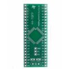
For 44 TQFP and more pins I use a breakout board .. depends on soldering skills :)
View attachment 115931
I may have to use the adapter. I suppose I could use a pair of mating berg headers and put some of the external logic underneath the PLCC addapter.
I'm pretty good with an iron, although these days, I have to take frequent breaks because my hands cramp up.

I have not gone down the external Xtal road.. internal + PLL good enough for most apps and has a 'osctune' reg .. and will do 16 MIPS ..(The dsPIC33 will do 140Mhz ( 70MIPS )

I'll grab crystals as well, and try both ways. Of course, I'll end up going with the scenario that involves the least amount of parts. :)

Re display I have found using a I2C - LCD back pack frees up several pins. you may need I2C EEprom chip too .
wkrug said the same thing. So I'm going to grab a display module and an EEPROM too. :)

was wondering how many 'keys' this keytar was having?

From what I've seen, keybeds run in standard sizes.

37 note, 49 note, 61 note, 76 note and 88 note.

The Alesis Vortex that I have is a 37 note keytar, but it's just not enough keys. The action is clunky and makes a lot of noise.
The functionality is really awesome. They do nice things with regards to program change and layering.

The Roland A49 is a 49 note MIDI controller It has a nice feel to it (I've always liked Roland key actions.)
The functionality is okay, but I couldn't just use it as it is. I have one and am going to use that keybed.

Take a look here.
http://www.openmusiclabs.com/learning/digital/input-scanning-matrix/xmem/index.html

I have a few 'ac573s, so I'm going to use this as a starting point. I still have to "buzz out" the keybed and draw up the connector.

This keytar is not an item that I'm looking to mass-produce. It would cost a small fortune to get a business like that off the ground.
When it is complete, we'll let some of our members here take a shot at mass-producing the board and selling it.

I have a few more MIDI project concepts, and, G_D willing, I'll share them here as well.

Myself I would like to see an open-source DIY MIDI board made available that could be used by anybody who wants to retrofit a keybed into another box.
Since it's open-source, the sky is the limit in terms what a circuit bender can do.

Don't get me wrong. I like money just as much as the next person does. But money is just a means to an end.
And like a hammer or an oscilloscope, it's just a tool.

The smile that you put on someones' face is priceless. :)

'nuff said. :)
 
Instead of tantallum capacitators You can use X7R SMD Capacitators too.
Thanks for the heads-up. My hands are not steady enough to do SMD, so I'm going to use thru-hole for this particular build.
When I'm counting right You have to have 28 Port Pins to readout an A-33 Keyboard with one controller.

This particular design will only support a 49 note keybed. I may end up going with a larger CPU. Perhaps the 24F32KA304.

granddad suggested I try going with the internal PLL. I wonder if that will give me 2 extra lines. ;)

I'm still going to buy 2 dsPIC33EVs :)
 
Last edited:
The 10UF is for the Vcap pin ... ( loose another I/O ! )

Yup. Just looked at page 25 of the KA304 manual. I grabbed the 24FV's because they were 5v.
If I grabbed the 24F series (3.3v), I'd have the extra I/O, but I would have to use a LDO regulator to get 3.3v

I do have one of these:
https://www.microchip.com/wwwproducts/en/MIC2941A
So I'll be placing another order at digikey later. :)

I'm not using any of the interrupts, so that frees up a few more I/O ports. :cool:

I'm going to try the internal clock too. It looks like I can get another 2 I/O pins.

I'm going to spend some time later and reverse engineer the 49 note keybed. Then I'll get a better picture of what I need.
 
Last edited:
Status
Not open for further replies.

Latest threads

New Articles From Microcontroller Tips

Back
Top