Shadow_warrior
Member
Hello everyone,
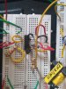
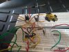
I am making a buck boost converter with TL494. Operating frequency is 250KHz. problem is that whenever I am increasing the duty more than 40% ,switch is getting burned. Note Input voltage is only 18 V and output current is 0.5A. I am using IRF540 . Inductor is 110uH. Can anyone tell the reason?
I am making a buck boost converter with TL494. Operating frequency is 250KHz. problem is that whenever I am increasing the duty more than 40% ,switch is getting burned. Note Input voltage is only 18 V and output current is 0.5A. I am using IRF540 . Inductor is 110uH. Can anyone tell the reason?
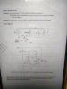
 Sim runs ok with open loop.