Continue to Site

Welcome to our site!

Electro Tech is an online community (with over 170,000 members) who enjoy talking about and building electronic circuits, projects and gadgets. To participate you need to register. Registration is free. Click here to register now.

  • Welcome to our site! Electro Tech is an online community (with over 170,000 members) who enjoy talking about and building electronic circuits, projects and gadgets. To participate you need to register. Registration is free. Click here to register now.

Brown Out Reset

Status
Not open for further replies.
Either add more capacitance or handle the brown out in software. Assuming you fix the problem with capacitance then how will you handle a brown out if it occurs due to a short mains failure. If you can work out how to handle a brown out in software then you could just let it happen.

Mike.
 
I've used a pair of 470uf caps on the Mongoose kit, similar design but no regulator. I run it from 4 AA NiMH batteries.

A small cap on the input side of the regulator should be all that's needed from a DC supply. I don't see the logic supply of the SN754410 connected in the schematic.

Note would it be possible to use a 12V stepper?
 
Last edited:
Hi Bill;

Yeah, probably similar 'cause I use your schematics as reference all the time! The regulator and caps came straight from the ICD2 schematic (I had a 0.33uF cap on the input side, as can be seen above -- which I changed to a 100uF). :) I always say I'm not a hardware guy, but I am learning -- and it's from guys like you -- thanks!

I will have a look at your Mongoose design.

blueroomelectronics said:
I don't see the logic supply of the SN754410 connected in the schematic.

Sorry, just want to make sure I understand you -- are you referring to Vcc1 (5VDC) supply? If so, they are hidden pins and connect when transferred to ARES. That is what C7 is for -- C6 is for the PIC.

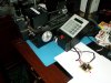
As for using a 12V stepper -- I don't understand why? The reason I chose a 3VDC stepper was because I could run it at 12VDC (which is the voltage that I have to work with -- I don't have the luxury of designing a 48VDC power source -- I have to work with what the machine offers) and limit the current to get speed and torque (I'll have to show you a video of what it does -- attached is an image though). Well, that, and it was readily available at Sayal! Again, I am a noob, so correct me if I am wrong, but you'll get nowhere near the same speed / torque from a 12VDC stepper, supplied at 12VDC.

As a final note, the stepper itself is not causing the brownout -- it is a DC motor (regular motor) that turns on to start the cutting wheel of the key machine. My 12VDC source is being supplied from the same source as this motor.

So, according to your comments, I should be concentrating on a larger cap on the OUTPUT side of the regulator, which feeds the logic. Do you know of any good explanations on caps? I keep reading on them, but I keep getting explanations on how they are made and how they work (which I understand) -- I just don't understand how to pick sizes -- how much "reserve" any particular cap will provide, etc.

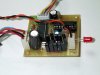
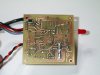
Oh, and for those interested -- here's the process I used to create the PCB --> https://www.electro-tech-online.com/threads/my-first-home-made-pcb.33911/.
 

Attachments

  • DCP_5773.JPG
    DCP_5773.JPG
    183.3 KB · Views: 166
Last edited:
What happens if you increase C3? 470uf @ 6.3V come in small sizes and they sell really tiny 0.022F 5V caps on College and larger 1F at Active Suplus.
Also the cap your using may have a high ESR.

PS what's suppling the 12V DC?
 
Last edited:
As you have a blocking diode it is better to add capacitance to the 12V side as it will hold more energy in that position unless you can get the small 6.3V cap suggested by Bill. One other solution may be to move your power LED to before the diode as this appears to be your main load.

Have you considered my suggestion of handling the brown out in software? In this case it would seem to be the best solution.

Mike.
 
@Bill --> I haven't tried increasing caps any further as I ran out of time yesterday -- plus, I had to pick up some bigger caps. I'm going to experiment a little this aft/eve.

The key machine itself provides the 12VDC -- it's a 110V machine which supplies (through an internal transformer) 12VDC @ 10A for the DC cutting motor and internal stepper.

@Mike --> No, honestly, I have not yet thought about your approach, hence why I have not responded. I am not quite sure what you are referring to by handling it in software -- so, rather that ask stupid questions, I thought I'd research it a bit first.

Thanks for the tip with the LED -- it's not really needed, it's simply there to tell me that it's getting power. I'll disconnect it altogether and see if it helps.

As for the blocking diode -- it's been added to the schematic AFTER the board was built. The board does not have the blocking diode. The MCLR diode / resistor was also replaced with a jumper as it should not have made it to the board.

Thanks for your replies -- I'm sure to ask a few more questions after I first do a little research into both your replies.

Kyle
 
Don't need the blocking diode, it's nice though as it'll protect the 7805 if you reverse the power supply. A meter that records min & max voltage would be a help.
 
blueroomelectronics said:
Don't need the blocking diode, it's nice though as it'll protect the 7805 if you reverse the power supply. A meter that records min & max voltage would be a help.

I would disagree - D4 is pretty well essential, as is a much larger C5 - this allows C5 to power the circuit if the supply dips, and the blocking diode stops the external circuitry discharging C5. It's a standard method to help prevent high current surges (from motors etc.) crashing the PIC.
 
Thanks for the information, Nigel. I have picked up some various caps to have around -- here's a list of what I grabbed today;

.22uF 25V
.47uf 50V
.68uF 50V
47uF 25V
220uF 25V
330uF 50V
470uF 35V

470uF 6.3V
1000uF 6.3V


@Mike --> I really haven't looked into the software idea yet -- but have been thinking about it. From what I can gather, you are referring to detection of the BOR status bit to tell me whether we have recovered from a BOR condition and act accordingly. The only part that is not clear is how to tell where I am at any given time -- what part of the software I am in when the BOR occurred. I can assume that it happened right when the motor turned on, so I would know where I was. Hmmm... I guess I could set a flag to say the cutting motor is running and if the BOR status bit is detected while the cutting motor is on, send it back to when it should be. Ah, there's probably lots of ways -- I'm just trying to see if I understand where you're coming from (options, man!). :)

blueroomelectronics said:
A meter that records min & max voltage would be a help.

Sure would -- I'll have to look into that. Hmmm... maybe a neat PIC project.... :)
 
Problem solved! :D

A 470uF 35V cap was added (C5) on the 12VDC source, before the regulator -- the trace was then cut on the bottom solder from pin 1 (12VDC) of J1 to C5 -- a 1N4004 (that's the smallest one I had on hand) blocker diode was then soldered across the gap from J1 to C5 (+).

I started with a 470uF (up from a 100uF) -- I don't know what size is actually required, so I guess one day I'll have to reduce the cap until it browns out to see my threshold.

Images are attached of the mod. (And the other resistor you see on the back in a pullup I forgot for the push button! Doh!)

Thanks again for all your help.

@Mike --> I'm still interested in hearing from you, so don't think the thread is closed! :D
 

Attachments

  • DCP_5774.JPG
    DCP_5774.JPG
    129.8 KB · Views: 153
  • DCP_5775.JPG
    DCP_5775.JPG
    160.5 KB · Views: 178
Status
Not open for further replies.

Latest threads

New Articles From Microcontroller Tips

Back
Top