Continue to Site

Welcome to our site!

Electro Tech is an online community (with over 170,000 members) who enjoy talking about and building electronic circuits, projects and gadgets. To participate you need to register. Registration is free. Click here to register now.

  • Welcome to our site! Electro Tech is an online community (with over 170,000 members) who enjoy talking about and building electronic circuits, projects and gadgets. To participate you need to register. Registration is free. Click here to register now.

Breath sensing circuit

Status
Not open for further replies.

NSKL

New Member
Hello everyone,

As I noted in one of the previous posts, I'm working on a project with a couple of different people. We hit a bump, and we're not sure what the best solution is, so I would like to hear some more opinions please.

We need to design a circuit which will sense the strength of breath (airflow) and adjust the volume of an amp accordingly. Think of it as an electronic flute. The harder you blow on the mouthpiece, the louder it should sound.

We've been looking at a number of different approaches to sense breath strength.

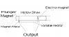
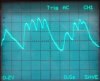
1) Using a DC motor in reverse. Putting a propeller on the spinning end of the motor, when someone blows over the propeller and spins it, the motor (generator) will output a voltage spike. Problems with this approach is that it takes considerable breath strength to get the propeller to spin initially. In addition, the voltage output is rather jagged when viewed on a O-scope and hence we're afraid this will cause spikes in the volume as well, which is not desirable

2) Using a pressure sensor such as MPXV5010. This should work fine, except the user will not be able to blow through it. It would feel like blowing in a straw while u keep the other end of the straw closed. This is ok, and it should work fine in theory, but pressure sensors go for about 40AUD which is expensive for our budget. Therefore an alternate and cheaper solution is desirable.

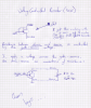
3) Using a airflow circuit shown here: **broken link removed**
We still haven't built a prototype of this, so I can not comment on the quality of it as a solution.

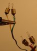
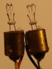
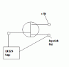
4) Using a mechanical solution. We've taken a slider pot, and attached a "wing" to it, and a spring. The spring keeps the slider pot at maximum resistance, and when someone blows into the mouthpiece, and into the "wing" of the slider pot, the pot slide moves and lowers the resistance. When there is no breath, the spring pulls the slider pot back to maximum resistance. This works, but it is not sensitive enough. It's hard to calibrate the spring to be sensitive enough AND strong enough to pull the slider pot back to maximum resistance when there is no breath. Therefore, this solution partially works, but more sensitivity is desired.

All these solutions seem pretty complicated to me, and since PCB space is an issue, we have to try and keep it as simple as possible. So I would like to hear if anybody has any ideas or suggestions in regards to this.

Thanks for reading,
-Igor
 
Most of your theories will not work for the fact they will not respond quick enough if you're talking about responding quickly to changes. As far as the pressure sensor idea you can find cheaper pressure sensors.

However a better and cheaper way would probably use a reed. Possbily a bi-metal material or something that would change voltage as it bent from air flowing past it. That or have a reed that moves with the air next to another conductive post that doesn't move. Then you could sense the capacitance difference as the movable piece move closer or further away from the stationary piece.

Another option is like what they use for some wind sensors. You heat a metal element with a steady current. As air blows past it the air flow will cause it to cool down quicker. You have a temperature sensor connected to it to measure the temperature as more air flow should reduce the temperature of the element. Probably not as responsive as the reed version.

Let us know what works.

Michael
 
The response time or #3. will be very slow. You might look into something similar: hot wire flow sensors or hot wire anemometers. There is a very basic one in a Forrest Mim's publication using a light bulb filament:

https://books.google.com/books?id=-...Kse2Rx9&sig=SniBMdhV_Kn5X_eOhgBelcsBKeE&hl=en

If two filaments were used instead of the resistor and filament in the half-bridge sensor, one in still air would compensate somewhat for differences in ambient temperature. I've played just a little with this concept, and the response time is very quick.

Ken
 
I've had decent luck in the past using a simple mic element and preamp. Bury the mic in the wind tube so that any air flowing through the tube flows over the mic, and use the resulting amplitude out from the preamp to set your level.

If you try this, use a mic which won't mind humidity or shield it fro direct breath exposure with a bit of cling wrap or something. May or may not work for what you need, and can be sensitive to crosstalk (handling the case, etc).

Alternately, what kind of DC motor did you try? A pager or toothbrush motor seems like it should be fine. The problem might be more that it doesn't stop immediately when you remove the breath input, but it might stop soon enough for your purposes.


Torben
 
Hello Everyone,

Thanks for the replies. I think we will go and build a prototype of the anemometer suggested by KMoffett and see if it works well enough. I've also went out and bought a computer CPU colling fan, so we will give that a go as well. I have an old toothbrush as well, so I'll take it apart and try that motor as suggested by Torben.

We thought of using a mic, but we believe it might be too sensitive too ambient noise and we're afraid it will give too much of a jagged voltage output which will be hard to "normalize" to get a good enough reading out of.

The response time is not critical. We can accept a response time of about 0.5 seconds.

I haven't considered a reed, (to be honest I don't know what a reed is) so I will look into this as well.

Once we decide what mechanism to use, we're thinking of either using a FET as a voltage controlled resistor to control the gain of the amplifier and thus volume. Alternatively, we will be using a microprocessor to deal with input and proper frequency generation for the different notes, so we're thinking we can also feed the voltage output of the breath sensing module into the ADC of the micro controller (and AVR atMega), and get it to adjust volume through software, but this might be too slow.

In any case, I'll post back when we build and test some prototypes in the next couple of days.
Thanks for all the help and suggestions guys, it is much appreciated.
-Igor
 
Hello Everyone,

In the past couple of days I've built some prototypes to try to tackle the problem of sensing breath. The breath strength needs to be used to adjust the output volume in our project.

The prototype uses a DC motor (a small CPU cooling fan) set up in a closed box with blow holes (with a mouthpiece) which directs the air at a right angle to the blades of the cpu cooling fan. A moderately breath is enough to spin up the dc motor. The only problem with the DC motor is that it doesn't stop immediately when the breath is removed, but this should be acceptable.

Then we feed the voltage generated by the DC motor into a Phillips TDA7052A audio amplifier (through a capacitor which smooths the voltage a bit). The TDA7052A has a DC voltage regulated gain (volume). Datasheet can be found here: https://www.electro-tech-online.com/custompdfs/2008/04/43870.pdf

Therefore, the voltage output from the DC motor (generated by breath input) is fed into the amplifier to control gain. This works decently well, but I would like more control over voltage level outputs. The TDA7052A DC voltage gain control accepts values from 0v (no gain) to 4v (maximum gain). I was wondering if there exists some device which we can place between the dc motor output and the amplifier input which will give us more control over amplifier gain, and make it more "step-like".

I have never used an ADC, but would this serve our purpose? Can we feed the voltage output from dc motor to ADC which will sample it at, say, 10Hz, and output a flat DC voltage corresponding to the sampling of the dc motor voltage?

Or is there some other way to achieve the desired result?

Sorry if this description is a bit confusing, and thanks for reading!
-igor
 
Google: Operational amplifier

These are IC's that will allow you to set the gain and polarity.

Ken
 
A toothbrush motor is pretty strong and used as a generator it requires a high momentum to start rotating. An alternative motor would be a solar toy motor. They are very small and start rotating at considerable speed already at 0.8V. They turn very easily when connected to a propeller (impeller) and generate a usable voltage too.

I have some small samples which I could ship to you in an envelope free. You will probably run into a problem trying to mount an impeller to the shaft. It's just one mm diameter and 3mm long. For details please refer to the little Eagle drawing.

For accurate measurements I suggest a simple brake by shorting the motor. Push a button to "release" the break. Start breathing and as soon as it is finished release the button to activate the brake. You can find out experimenting a bit how many rotations the motor will perform after the brake is applied and use the result as a correction factor.

Kind regards

Hans
 
Last edited:
Thanks for the replies guys,

Boncuk: I managed to find a small cpu cooling fan from one of those "garbage reversal" places, and it works very well, but thanks for the offer to ship me that motor anyway.

I had a chat with some electrical engineers at my university and they reckon I could solve most problems by constructing an appropriate low pass filter to remove voltage ripples (which occur only at certain RPMs of the motor), and then a simple OP-AMP to amplify the signal before feeding it into the audio amplifier.

I'll have some time this weekend to work on this and I'll post the results. Also, this is a university project I'm working on, so I'm not allowed to post any schematics I made before the end of the course. So when the course ends I'll post the schematics of the whole project and a project description in case someone might find it useful.

Thanks for helping,
-igor
 
heres a very simple analogue solution.
Place a kind of like a loose fitting plunger in a tube.

The plunger is attached to a sliding resitor which when the plunger is pushed foward it decreases the resistance.
Im thinking about an electro-magnet which when activated repels the Plunger (which is a small round magnet) back in position.
The activation can be a switch before the variable resistor which is connected to a small capacitor to act as a time delay, then turns on the electro magnet and therefore puts the slider back into position.
 

Attachments

  • breath strength.JPG
    breath strength.JPG
    32.3 KB · Views: 366
Since we're still playing with ideas, I thought I'd try the hot wire flow sensor I mentioned earlier. I used 4 pilot lamps (#1815's: 14V@2.8W...I had a bunch) in a full bridge configuration. The glass envelopes were removed to expose the bare filaments. Two of the lamps are in the air flow path, and two are in still, ambient air. The saw teeth are puffs during a continuous blow. I just ran the output to an O-scope, but it could be fed to the differential inputs of an op-amp for offset and gain adjustment. A higher bridge drive voltage (4v) gave a higher output and was more sensitive, but a longer decay.

Ken
 

Attachments

  • BreathBridge.gif
    BreathBridge.gif
    10.4 KB · Views: 420
  • BreathBridge.JPG
    BreathBridge.JPG
    30.2 KB · Views: 294
  • BreathSensor.JPG
    BreathSensor.JPG
    34.9 KB · Views: 378
  • BreathWave.JPG
    BreathWave.JPG
    41.6 KB · Views: 281
Fet as resistor

NSKL..You wrote..."Once we decide what mechanism to use, we're thinking of either using a FET as a voltage controlled resistor to control the gain of the amplifier and thus volume."

Can you post a diagram/circuit on how to used a FET as a voltage controlled resistor. ? Which FET are you going to used?

I am working in a MIDI controller and the circuit I am using Electret Mike->OP Amp->LED->Photoresistor does not work quiet well. I need to generate resistance for this application.

Thanks
 
prprog,

I've attached a simple circuit showing how I hooked up a FET to work as a VCR. Pretty simple, but keep in mind resistance decreases as voltage increases in a non-linear way.

HTH
-Igor
 

Attachments

  • FETvcr.png
    FETvcr.png
    311.9 KB · Views: 335
Fet as voltage control resistor

NSKL. Thanks for the circuit. But I am not sure (and dont want to make a mistake here) how to hook it to the game port of my PC. This will be the substitute of an analog joystick, specifically the potentiometer. Lets see if I undertood it -> In your diagram "drain" will be the +5V , "Source" will be the Pot connection and then you also connect this to GND (I feel a bit worry about this connection) . Then a voltage to the "Gate" will control the resistance. Is this correct? Do I need a resistor somewhere to protect the PC game port? Thanks a lot.
 
Hi prprog,

I don't quite understand what you want to do. Perhaps a circuit diagram will help. In any case, what we did in the labs, is connect a ohmmeter across drain and source, and by applying different voltage levels between the gate and source, we observed a inverse relationship between drain-source resistance and gate-source voltage. i.e. as voltage across gate-source increases, the resistance between drain-source decreases (non linearly).

These are our practical results from fooling around in a lab one day. See attached document for theory.

HTH
-NSKL
 

Attachments

  • VCR.pdf
    33.6 KB · Views: 479
FET as Voltage control resistance

NSKL. I try the attach circuit (well a circuit in concept), but I don't get changes in resistance, or at least the joystick port does not read it as I expected. Actually the pot value does not change at all. Any suggestions? If I am using +5V from the PC port , what voltage should I supply to the FET Gate to make it behave as a resistor? Thanks.
 

Attachments

  • FET_Resistance.GIF
    FET_Resistance.GIF
    2.8 KB · Views: 276
Hello!

I have seen the broken bulb idea before, but instead of two they used a single bulb. The circuit preheated it to certain point with a little voltage (maybe as a point of reference), and then if the wind blew the circuit measured the resistance change across the filament.

I tried to find the original schematic but I failed, anyway I guess all of you are experts so making the circuit is piece of cake!
 
Menticol,

Which circuit were you looking for? If it was the single-bulb detector, I included a link to it in my first post in this thread. The four-bulb heated-bridge gives twice output of the single-bulb and two-bulb, and also compensates the zero point for different ambient temperatures, as does the two-bulb half-bridge.

Ken
 
Ok, so I've finalized the circuit which uses breath sensor to adjust the volume of an amplifier. I played with a lot of ideas using piezo films, DC motors in reverse as generator, and electret microphones. All these devices can be used as breath sensors, but I had the most success with the piezo film. A very rough schematic of my piezo film circuit which controls the volume (gain) of an amp depending on breath input is attached below if somebody ever needs something similar. I also made a circuit which uses a DC motor in reverse to control volume, and works very well, but due to mechanical resistance of the motor bearings, it takes an initial strong breath to get the motor started, and therefore I discarded this idea and adopted the piezo film circuit shown below. If anybody would like to see the DC motor circuit for breath sensing let me know and I'll post it.

I would like to thank everyone for their help. The description of the project I am working at can be found at: **broken link removed**

For obvious reasons I can not yet post the whole project circuit, but I'll post it once the course finishes.

Again, thanks for all the feedback, this forum has been a great resource.
Cheers,
-NSKL
 

Attachments

  • piezo.png
    piezo.png
    10.6 KB · Views: 422
Status
Not open for further replies.

Latest threads

Back
Top