Continue to Site

Welcome to our site!

Electro Tech is an online community (with over 170,000 members) who enjoy talking about and building electronic circuits, projects and gadgets. To participate you need to register. Registration is free. Click here to register now.

  • Welcome to our site! Electro Tech is an online community (with over 170,000 members) who enjoy talking about and building electronic circuits, projects and gadgets. To participate you need to register. Registration is free. Click here to register now.

Blinking!

Status
Not open for further replies.

Electronman

New Member
Hi,

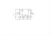
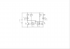
Today after getting several advices from audioguru I went to make a flasher based upon "cut off" and "saturation" regions of BJT transistors (I think it does work based upon those regions though!)
1: I would like to know if my design (resistor values) is just correct??
2: I want to know how to calculate the values for both capacitors (I think I have a RC circuit, if so how to calculate the values for say 2 seconds of blinking??)
3: My simulator does not show any blinking for the LED's with these used values and both are lightened simultaneously!? What's the problem really??!

Hope you guys specially professors "audioguru" and "MrAl" help me out to learn to design these switching circuit (though I am a newbie but I know the formulas for RC time constant circuits and Cut off/Saturation situations of a BJT)
 

Attachments

  • 55.PNG
    55.PNG
    16.6 KB · Views: 248
I changed the values and now it blinks! So it seems to me that it does not follow the cut off/saturation conditions? What is your idea???
 

Attachments

  • 44.PNG
    44.PNG
    5.1 KB · Views: 170
In a simulation program both transistors are identical so they turn on at the same time then stay turned on.
But in the real world one transistor will have more gain than the other and it will turn on first which starts the two transistors to oscillate.

Frequently the circuit being simulated must be "kicked" to get it working.

The simple circuit does not "blink" the LEDs. Intead is alternates which LED is turned on. The average current is the same as one LED that is continuously lighted.

EDIT:
The supply voltage is too high. The max allowed emitter-base voltage of the BC108 transistors is only 5V. The bases are tried to be driven down to -10V which causes avalanche-breakdown of the emitter-base junctions which is bad for the transistors and changes the calculated timing.
The supply for the circuit that drives 2V LEDs is 7V max.
Diodes can be added to stop the avalanche-breakdown.
 
Last edited:
Ok, we have change the BC 108 by every another NPN transistor which does work, Now I would like to be able to analyze and specially be able to calculate the time constant for a such circuit.
I googled it but google was unable to give me any result with formulas!

P.s I think I am able to see what you are saying about identical transistors in simulator, but it worked when I change the values to the second pic
 
Last edited:
"The simple circuit does not "blink" the LEDs. Intead is alternates which LED is turned on. The average current is the same as one LED that is continuously lighted."

Sorry I am not able to understand this, My poor english:eek::(
 
I googled it but google was unable to give me any result with formulas!
There are many websites that have the formula for the timing.
But your circuit has its supply voltage too high that causes avalanche breakdown in the transistors that makes the formula useless.
 
"The simple circuit does not "blink" the LEDs. Intead is alternates which LED is turned on. The average current is the same as one LED that is continuously lighted."

Sorry I am not able to understand this
The circuit turns on one LED then it turns it off and turns on the other LED. There is always one LED turned on so the average current is the same as if one LED is lighted continuously.
A blink is for a very short duration then the average current is very low.
 
There are many websites that have the formula for the timing.
But your circuit has its supply voltage too high that causes avalanche breakdown in the transistors that makes the formula useless.

I do know the formula for RC timing circuits but I want (and googled the formulas related to our above 2 transistor flasher circuit, I got no results for it though.).

Ok what about reducing the power supply to 8V or 6V or even 5V? I just want to learn how to design, so It is not so matter to me if we change and reduce Vcc, or the transistors with better ones(I just want to learn..)
 
Last edited:
The circuit turns on one LED then it turns it off and turns on the other LED. There is always one LED turned on so the average current is the same as if one LED is lighted continuously.
A blink is for a very short duration then the average current is very low.

So I seem to do not know the real meaning of Blinking in english right?!:)
 
If you don't know English then you can chat in your own language in your own country.
We chat in English here.

Lol, Are you thinking that my english is too bad to do so?
Maybe I do not understand the exact meanings, but you understand my meanings thought, right?;) My English is much better than my native Language lolllllll
 
Last edited:
I am in Canada where 15% of the people speak nothing but French but I can't speak French.
 
I am in Canada where 15% of the people speak nothing but French but I can't speak French.

but here 1% people speak English and I am able to do so too (Amazing).

But please tell me if I am not understandable to you and to other guys here by my English (If so, Then I'll leave this forum, But please wait, i'll do so just after somebody teched me how to calculate the time constant for this flasher though;):)?)
Besides as I told before I noticed that this flasher does not change from cut off to saturation which you teched me how to calculate the LED voltage for it too!?
 
Lol,
Audioguru, I got a Reputation for this thread contained "Thanks alot for your post (MRF)"
So What does 'MRF' means?lol
How can I find out who has given me this Reputation?
 
Your English is pretty good.
Reduce the supply voltage of the circuit to 6V then look for Transistor Multivibrator in Google. Be careful because a few links are wrong with the polarity of the capacitors backwards. The calculations are shown.
 
Your English is pretty good.
Reduce the supply voltage of the circuit to 6V then look for Transistor Multivibrator in Google. Be careful because a few links are wrong with the polarity of the capacitors backwards. The calculations are shown.

Thanks, But I was disappointed when you wanted me to talk to my native countrymen!
Ok, thanks, Now I am searching for the keyword you gave me, Will let you know if I would not get good result though!
 
I found this:
**broken link removed**
It contains the formula for calculating the freq of the circuit but It has nothing about how to really calculate and reach to that formula!
It is not so good for me as a learner.
 
Hi there,

What is it exactly you want to know about this circuit?

You probably already know that when the cap charges it charges close to
the full supply voltage, and when the transistor who's collector connects to
that cap goes low (turns on) you end up with a very negative voltage at
the base of the other transistor, and many transistors like this are only
rated for about 5v for reverse Vbe.

That aside, you need to calculate the time constants that result from the
way the circuit is connected. You can start by assuming one transistor is
already turned on and the other turned off, and the voltage levels that
result from that initial setup.

Another idea is to put resistors in series with the caps, which would require
two more resistors. This gets you a longer time constant for the price of
two resistors instead of larger caps. That also can solve the reverse bias
Vbe over voltage that results from the cap charging up as mentioned above.

Some circuits are easier to analyze than others. This one has some non linear
features which may be a bit harder to deal with for exacting calculations.
 
Last edited:
Cry,!

This is the second circuit which I want to analyze to learn how to calculate the RC time constant of each stage, but they seem to end with fail!

About this circuit:
1: I want to know if it is a good idea to design and run the LED's in cutoff/saturation state or no (Suppose I want to start and design it from zero, stage to stage. ie designing and running a led by a transistor then adding more stuff...).
2: I want to know how to calculate the Time constant for the circuit?
 
R (ohms) times C (farads) is one "time constant". The resistor charges the capacitor to 63% of max in one time constant and the capacitor is 99% fully charged in 5 time constants.

The simple two-transistors multivibrator circuit you posted saturates then cuts off each transistor if the supply voltage is reduced.
 
Status
Not open for further replies.

Latest threads

Back
Top