Continue to Site

Welcome to our site!

Electro Tech is an online community (with over 170,000 members) who enjoy talking about and building electronic circuits, projects and gadgets. To participate you need to register. Registration is free. Click here to register now.

  • Welcome to our site! Electro Tech is an online community (with over 170,000 members) who enjoy talking about and building electronic circuits, projects and gadgets. To participate you need to register. Registration is free. Click here to register now.

BLDC moto Dynamometer design

Status
Not open for further replies.

misterT

Well-Known Member
Most Helpful Member
Hi, this is a project for my university.. not a student project or a school assignment, but an academic project for research (I do not get paid for this). We are looking for this project to benefit us in some upcoming robot competitions.

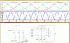
We need to evaluate DC motors, and I've seen this kind of problem here at ETO, and at my university, quite a few times. Below is my design for a simple "good enough" dynamometer for testing hobby brushed and brushless DC motors and maybe other cheap DC motors. The design is for brushless motors with Y winding.

Simply put.. there is a BLDC motor with electronic speed controller (ESC) which drives an identical motor connected as a generator. The generator load is purely resistive. The flywheel provides the reactive load. Flywheel is supposed to be constant, but the resistive load needs to be variable.. either in steps or smoothly. This setup can act as a simple test-bench of a dc-motor driven vehicle.

dyno_dynamometer-png.75647


All input is welcome, but I have few specific questions:

1) Can I treat the node labeled "common" the same as "Neutral" of a traditional 3-phase generator.. normally the neutral would be the point where all the generator coils are connected together (middle of the motor drawing). I would like to treat this "common"-node as reference point for all measurements for the generator (current and voltage.. and frequency). The goal is to measure the power generated (and consumed by the resistors) and the (peak) voltage generated. Is my idea ok? All resistors are the same value.

2) How could I implement an electronic control of the load? Simple way would be to use relays to switch parallel resistors on/off for each resistor. But, is there a clever/simple way to get more control of the load (smooth ramp of increasing load)?
- Could I tie the "common" node to a solid ground (power supply ground) and use FETs to bypass resistors with high-frequency PWM? Or, to connect resistors on/off with fets. Will the FET intrinsic diodes be a problem?

3) Any comments on the drawing.. any mistakes? I'm rusty on mechanical design and combining electrical and mechanical design is kind of awkward. I kind of winged the "synchronized control of load resistor" -part. Anyway.. this is just a concept drawing.

The motors are identical.. at least for the first prototype.
There will be a microcontroller etc. to take all measurements. The final calculations will be done offline on desktop computer. That is no problem. I can provide all that when the project is done.

Dyno_Dynamometer.png
 
Last edited:
Why not use a three phase bridge rectifier to convert the 'generator' output to DC and then to a single resistor? Instead of three individual resistors.
 
The 'common' point will have the same voltage as the centre of the generator star connection, and the 3 phases will oscillate about it.
Yes, the diode in the FET will cause trouble if the phase voltage becomes negative (~ < -0.6V) as it will conduct. I don't think direct PWM driving of a FET in line with the load resistor will give you what you expect. The motor may not be able to supply the peak ON current (so your response will not be linear). You'll also get large voltage spikes when you turn the FET off (you can filter these using a capacitor, but that will change the loading).
The relays and resistors will of course work. You can also use a buffered opamp (or power opamp) in trans-resistance mode (one for each load resistance) and adjust the resistance using a digital pot or PWM through an analogue MUX.

The option shortbus provided sounds good and simple if the effect of the diodes can be ignored in your application.
 
Thanks for the feedback and suggestions. I think I keep it simple at first.. simple manual switch to change the resistance. That should give a nice step response.
 
Just thought of maybe another problem using a BLDC as your 'generator'. A BLDC motor has both salient stator windings and salient magnets in the rotor, so it won't give a true three phase output. Don't know if that will effect you needs.

A lot of dynamometers use an eddy current power absorber. This could be made using a disc of copper or aluminum and some permanent magnets. Just an idea for you to consider.
 
Just thought of maybe another problem using a BLDC as your 'generator'. A BLDC motor has both salient stator windings and salient magnets in the rotor, so it won't give a true three phase output. Don't know if that will effect you needs.
We are not using the power for anything "useful" so the quality of the waveforms does not matter. We are just absorbing the generated power.. and trying to control the load so that we can take meaningful measurements.
I made some measurements already and I think the waveforms of the generator looked pretty good. The phases are 120 degrees apart and "sort of" sinusoidal.. at least sinusoidal enough that I can apply all the math assuming sinusoidal waveforms.
BTW.. I have no idea what you mean when you say that BLDC has "salient magnets" and "salient stator windings".. could you elaborate.

A lot of dynamometers use an eddy current power absorber. This could be made using a disc of copper or aluminum and some permanent magnets. Just an idea for you to consider.
Yes, we are planning to add electromagnet "eddy current brake" to the flywheel.. but not for the first prototype. I think we even leave the flywheel out of the first prototype.
 
Last edited:
Rather than use 3 load resistors couldn't you just use a single resistor between 2 windings and ignore the third winding?
 
Rather than use 3 load resistors couldn't you just use a single resistor between 2 windings and ignore the third winding?

No.. That does not work in this application. It would make all the measurements more complicated. And it would not provide even load through one rotation.
 
hi T,

This method uses a resistive virtual centre point for your measurements.

The Winding inductance and frequency I have chosen are arbitrary just for the Sim.

E
 

Attachments

  • AAesp03.gif
    AAesp03.gif
    50.8 KB · Views: 482
BTW.. I have no idea what you mean when you say that BLDC has "salient magnets" and "salient stator windings".. could you elaborate.

Salient in a motor means basically single. A three phase generator/alternator or motor has the stator windings interleaved or over lapped between the coils. A BLDC motor has single coils for each phase of the motor. Not to mean there are only three coils but each phase is separated and not overlapped no matter how many coils in a phase.

And in a three phase alternator, like in a car, the rotor magnets are triangular shaped, not rectangular like a BLDC. The triangle shape rotor poles, some times called a"claw rotor", also helps to give the output a sinusoidal wave form.

Thanks for that info. I did not know that detail.. or that subtle difference between generator design and motor. I'll keep that in mind when I do my next measurements with the motors.. if I can spot something in the waveforms that relate to this.
 
hi T,

This method uses a resistive virtual centre point for your measurements.

The Winding inductance and frequency I have chosen are arbitrary just for the Sim.

E

Thanks for the simulation.. very neat job as always. I'll have to consider rectifier and single resistor (like shortbus= suggested, and you simulated). At least try it. I wan't to measure all phases anyway, but the load would be is easier to control with a single resistor..
 
Thanks for the simulation.. very neat job as always. I'll have to consider rectifier and single resistor (like shortbus= suggested, and you simulated). At least try it. I wan't to measure all phases anyway, but the load would be is easier to control with a single resistor..

hi T,
The 3, 10K's are only there to provide a 'common' point , you asked in your 1st post 'can I use the centre point of the windings', using a virtual common centre point, you can.

The 100R is the Sim load resistor.

The load resistor 'value' could be controlled by using NMOS FET's and Gate opto couplers to give load isolation, say PWM.

E
 
Here is a photo of my first setup. I don't have a good rig for the motors yet. It is "under construction".. just had to keep the motors down by hand.. squirmly setup :) Sorry I did not get a picture of the scope screen. The coupling is a simple plastic tube that fits snugly to the two pinions.
DSCF8280.JPG

That small ESC is supposed to give 60A continuous.. I'm "little" suspicious about that. We have backups.. so I will test it to the limit.
 
Last edited:
Hello, I am working on similar problem. Could you solve this problem? It would be great help if you you let me know the solution. Thank you !
 
Old thread, but one way to make a cheap yet highly effective eddy current braking/dynamometer load is to simply use a common AC induction motor and feed a variable DC power into its windings.

I've done it before and it works well. For short duration work 1 or so HP single phase motor can keep a 8 - 10 HP gas engine pulled down to a near stall until the rotor heats up too much.

Depending on how much braking capacity and run time duration you need most any AC induction motor will do the job rather well.
 
I did a similar thing a while ago. With 2 250W motors driven at 12V I calculated 175W going in and 125W coming out. Therefore, 25W loss in each motor or an efficiency of around (I think I calculated) 84%. I also tried full wave rectification but the overheating problems meant it was unusable. The heating is because you only draw current near the peak of the voltage wave and therefore you draw high current for short periods and have huge I²R losses.

Mike.
Edit, found a pic of the setup I used.
 

Attachments

  • 20170624_111450.jpg
    1.7 MB · Views: 222
Thank you for your replies ! Thank you Mike. I am planning to use this for fatigue testing of BLDC motors (250W) - It will run for at least a couple of hrs continuously. If suppose I provide regenerative circuit or resistance bank and provide cooling using industrial fan, can we get rid of heating problem?
 
If you use a resistive load then heating shouldn't be a problem. From memory I used three 50W 3Ω resistors in a star (Y) formation. I think it was these resistors.

Mike.
 
Status
Not open for further replies.

Latest threads

Back
Top