Continue to Site

Welcome to our site!

Electro Tech is an online community (with over 170,000 members) who enjoy talking about and building electronic circuits, projects and gadgets. To participate you need to register. Registration is free. Click here to register now.

  • Welcome to our site! Electro Tech is an online community (with over 170,000 members) who enjoy talking about and building electronic circuits, projects and gadgets. To participate you need to register. Registration is free. Click here to register now.

BJT uC switch problem

Status
Not open for further replies.

danielone

New Member
Hi all!

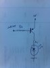
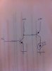
I made a simple BJT switch to control an array of LEDs with a uC. In attachment you find the simple schematic.

I have to control a current of about 510mA and the BJT I am experimenting with is a BCP53. uC supply is 5V.

I made two different version of the circuit:

1) If V+ is 5V and Rb is 220R the circuit works perfectly. When port is high LEDs are off and vice-versa.

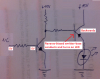
2) Then I hade to raise V+ to 15V. uC supply is indipendent from V+ and it is still 5V. This time the circuit does not work: if uC port is high the LEDs are ON and if uC port is low the LEDs are still ON. Resistor is still 220R but I also tried to raise and lower it. No change. It start working if base voltage is raised too to 15V but I must control the base with 5V from the uC.

I made this test with one only led ad 17mA of current.

I think BCP53 beta of 25 could be too low for my application but I cannot figure why it works if V+ is 5V and it stop working if V+ raised to 15V.

Do you think I can try with a Darlington pair? Something like a BSP 60

Many thanks for your kind reply! :eek:
 

Attachments

  • 2012-12-19 12.03.59.jpg
    2012-12-19 12.03.59.jpg
    2.1 MB · Views: 161
Your microcontrolller itself is not able to turn off a PNP switch at 15V. You might consider an NPN switching the base of the PNP or an NPN or N-channel mosfet by itself.

John
 
what do you think about using a Darlington instead?

You will still have the same problem. As John said you need to switch the base of the PNP with a NPN or use a NPN or mosfet with the emitter grounded and the led in the collector.
 
Hi I cannot use an NPN for switching because I have common cathode bicolor Leds. between cathode and ground I have a latch register that control which led is lit, then I have split supply for red and green with a PNP switch transistor on each arm. So I am forced to switch between supply and led anodes. I will try controlling the base of the PNP with a NPN. Something like this?

EDIT: or maybe a P-channel logic level MOSFET??!
 

Attachments

  • 2012-12-19 16.21.24.jpg
    2012-12-19 16.21.24.jpg
    1.7 MB · Views: 157
Last edited:
Hi I cannot use an NPN for switching because I have common cathode bicolor Leds. between cathode and ground I have a latch register that control which led is lit, then I have split supply for red and green with a PNP switch transistor on each arm. So I am forced to switch between supply and led anodes. I will try controlling the base of the PNP with a NPN. Something like this?

EDIT: or maybe a P-channel logic level MOSFET??!
Any PNP or P-MOSFET high-side switch requires a high voltage equal to the supply voltage to turn it off, which the processor can't supply. Two transistors as shown will work.
 
Yep, why a bjt? any particular reason, a bc547 and bc557 would be acceptable for controlling a 7 seg display.
 
I still need your help....i made the schematic with an NPN controlling the PNP...with 2N2222 as NPN and BCP53-16 as PNP it works for V+ < 10V. At 15 V+ led high-side switched by the PNP is always lit. Why? Vb of the NPN is 5V for ON and 0V for ground. :rolleyes:
 
Try connecting a pull-down resistor to the base of the NPN. It may be that the uC port output doesn't quite reach ground unaided.
 
I still need your help....i made the schematic with an NPN controlling the PNP...with 2N2222 as NPN and BCP53-16 as PNP it works for V+ < 10V. At 15 V+ led high-side switched by the PNP is always lit. Why? Vb of the NPN is 5V for ON and 0V for ground. :rolleyes:
Maybe you have the collector and emitter pins of the European transistor connected backwards (then the emitter-base has avalanche breakdown like a zener which makes it conduct). Their pins are the opposite of an American 2N2222 transistor.
 

Attachments

  • transistors.png
    transistors.png
    372.9 KB · Views: 140
Maybe you have the collector and emitter pins of the European transistor connected backwards (then the emitter-base has avalanche breakdown like a zener which makes it conduct). Their pins are the opposite of an American 2N2222 transistor.

Thank you very much for this suggestion! Tomorrow I will surely try to swap collector and emitter!

EDIT: audioguru you were right! The transistor was different from my datasheet and swapping emitter and collector it does work! You taught me once more that very often the simples solution is the right one! Many thanks!
 
Last edited:
Status
Not open for further replies.

Latest threads

New Articles From Microcontroller Tips

Back
Top