Hello there,
I'll start by saying I'm by no means an expert in electronic design, so please bear with me. Also my schematic and the datasheets I'm using will all be attached to this post.
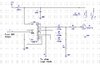
I'm designing a circuit whereby the output of a 4017B IC is driving a relay via a BC337-25 BJT Transistor (or maybe a MOSFET), but also want to ensure the output voltage remains high enough to drive other CMOS Logic Inputs. The circuit uses a 12V DC supply and the relay uses 140mA, my calculations for determining the base current are below (please correct me if they're wrong):
After the protection diode D1, the supply voltage for the circuit is about 12 - 0.7 = 11.3V.
Using the Minimum hfe value for BC337-25 from the datasheet of 160, with a collector current of 140mA I get a base current of 0.14/160 = 0.000875A.
To ensure saturation I've multiplied by a factor of 3 to get 0.000875 x 3 = 0.002625A = 2.63mA.
To determine the base base resistor I've used the VBE(on) value of 1.2V so the voltage across the resistor is 11.3 - 1.2 = 10.1V
I then get a resistor value of 10.1 / 0.002625 = 3847.62 ohms, so I've chosen a 3.9k resistor.
(Just realized I didn't take into account the voltage drop across the 1N4148 diodes so resistor value will probably be a little less)
What I want to determine is the maximum output current a 4017B can source and maintain a high enough voltage level to drive other inputs. I've looked at the Texas Instruments datasheet for the 4017B, on the second page in the Static Electrical Characteristics table. I'm reading the Min output high current with a 10V supply at 25 degrees C is 1.3mA or typically 2.6mA, with an output voltage of 9.5V, so I'm guessing it would still maintain a higher enough output voltage if I'm reading it correctly? I'd like to know how much the output voltage of the 4017B drops as output current increases and I'm guessing Fig. 7 probably tells you that but I'm not exactly sure how to read it, so if anyone could help me with that it'd be great.
So would a BC337-25 be appropriate for this or maybe I should pick a transistor with a higher gain like a BC337-40, or would it even be best to use an N-Channel mosfet such as an IRF510 perhaps?
My Schematic and datasheets are all attached below, many thanks for reading and helping me out.
CD4017B Datasheet: https://www.ti.com/lit/ds/symlink/cd4017b.pdf
BC337-25 Datasheet: https://www.onsemi.com/pub/Collateral/BC337-D.PDF
Schematic attached to post:
I'll start by saying I'm by no means an expert in electronic design, so please bear with me. Also my schematic and the datasheets I'm using will all be attached to this post.
I'm designing a circuit whereby the output of a 4017B IC is driving a relay via a BC337-25 BJT Transistor (or maybe a MOSFET), but also want to ensure the output voltage remains high enough to drive other CMOS Logic Inputs. The circuit uses a 12V DC supply and the relay uses 140mA, my calculations for determining the base current are below (please correct me if they're wrong):
After the protection diode D1, the supply voltage for the circuit is about 12 - 0.7 = 11.3V.
Using the Minimum hfe value for BC337-25 from the datasheet of 160, with a collector current of 140mA I get a base current of 0.14/160 = 0.000875A.
To ensure saturation I've multiplied by a factor of 3 to get 0.000875 x 3 = 0.002625A = 2.63mA.
To determine the base base resistor I've used the VBE(on) value of 1.2V so the voltage across the resistor is 11.3 - 1.2 = 10.1V
I then get a resistor value of 10.1 / 0.002625 = 3847.62 ohms, so I've chosen a 3.9k resistor.
(Just realized I didn't take into account the voltage drop across the 1N4148 diodes so resistor value will probably be a little less)
What I want to determine is the maximum output current a 4017B can source and maintain a high enough voltage level to drive other inputs. I've looked at the Texas Instruments datasheet for the 4017B, on the second page in the Static Electrical Characteristics table. I'm reading the Min output high current with a 10V supply at 25 degrees C is 1.3mA or typically 2.6mA, with an output voltage of 9.5V, so I'm guessing it would still maintain a higher enough output voltage if I'm reading it correctly? I'd like to know how much the output voltage of the 4017B drops as output current increases and I'm guessing Fig. 7 probably tells you that but I'm not exactly sure how to read it, so if anyone could help me with that it'd be great.
So would a BC337-25 be appropriate for this or maybe I should pick a transistor with a higher gain like a BC337-40, or would it even be best to use an N-Channel mosfet such as an IRF510 perhaps?
My Schematic and datasheets are all attached below, many thanks for reading and helping me out.
CD4017B Datasheet: https://www.ti.com/lit/ds/symlink/cd4017b.pdf
BC337-25 Datasheet: https://www.onsemi.com/pub/Collateral/BC337-D.PDF
Schematic attached to post: