PG1995
Active Member
Hi,
Could you please help me with the queries in the attachment? Thank you!
Question 1:
It says, "Saturation is the state of a BJT in which the collector current has reached a maximum and is independent of the base current."
The word 'saturation' suggests a situation or point beyond which no further increase is possible.
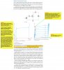
You can see that in the saturation region, Ic increases for increasing value of Vce until point 'B' where saturation occurs for the given value of Ib; and from point 'B' onward there is no further increase in Ic for increasing value of Vce.
In my opinion, the phrase 'saturation region' is not a good descriptive word because Ic does increase between the point 'A' and 'B'. Yes, 'B' is a point where saturation occurs and hence should be called ''saturation point'. Further, on the contrary, the region between points 'B' and 'C' is more of a saturation region than a active or linear region because Ic doesn't increase. What's your opinion on this? Perhaps, the choice of this terminology has to do something with amplification using BJT.
Question 2:
As it says that saturation is the state of a BJT in which the collector current has reached a maximum and is independent of the base current. I don't see how it's independent of base current. You can see that all three points 'X', 'Y', and 'Z' lie in the saturation region but still value of Ic is different for each point.
Question 3:
In the cutoff region, Ic is not entirely zero. Is this leakage current?
Thanks a lot for your help.
Could you please help me with the queries in the attachment? Thank you!
Question 1:
It says, "Saturation is the state of a BJT in which the collector current has reached a maximum and is independent of the base current."
The word 'saturation' suggests a situation or point beyond which no further increase is possible.
You can see that in the saturation region, Ic increases for increasing value of Vce until point 'B' where saturation occurs for the given value of Ib; and from point 'B' onward there is no further increase in Ic for increasing value of Vce.
In my opinion, the phrase 'saturation region' is not a good descriptive word because Ic does increase between the point 'A' and 'B'. Yes, 'B' is a point where saturation occurs and hence should be called ''saturation point'. Further, on the contrary, the region between points 'B' and 'C' is more of a saturation region than a active or linear region because Ic doesn't increase. What's your opinion on this? Perhaps, the choice of this terminology has to do something with amplification using BJT.
Question 2:
As it says that saturation is the state of a BJT in which the collector current has reached a maximum and is independent of the base current. I don't see how it's independent of base current. You can see that all three points 'X', 'Y', and 'Z' lie in the saturation region but still value of Ic is different for each point.
Question 3:
In the cutoff region, Ic is not entirely zero. Is this leakage current?
Thanks a lot for your help.