Continue to Site

Welcome to our site!

Electro Tech is an online community (with over 170,000 members) who enjoy talking about and building electronic circuits, projects and gadgets. To participate you need to register. Registration is free. Click here to register now.

  • Welcome to our site! Electro Tech is an online community (with over 170,000 members) who enjoy talking about and building electronic circuits, projects and gadgets. To participate you need to register. Registration is free. Click here to register now.

BJT Mic Pre Inside Mic Wand

Status
Not open for further replies.
ronv,

The LM833N datasheet says, and I quote, "The LM833-N is internally compensated for all closed loop gains and is therefore optimized for all preamp and high level stages in PCM and HiFi systems."

I guess that means that we do not have to deal with the phase and amplitude nasties found in the LT1115. I suspect we could go without any caps on the feedback resistors. But I put some 22p on anyway. You know, belt and suspenders. What do you think?

Since I have decided to go with a regulated supply, I hope the simple voltage divider at the MIC will do the job. It supplies 8.2V to bias the MIC. What do you think?

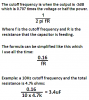
The FR curve looks very good. Straight as a string from 10 to 40K Hz. Only need 20 to 20K, but what the heck. It looks good.

I finally figured out how to get polarized caps on the schematic. Will you check the cap polarity to be sure I got it right?

Is the gain spread between the stages where it should be?

Any improvements you can think of?

I really thank you for all your help with this. I hope it has not been too boring for you.

Below is a pic and I have also included the LTS file if you want to give it a try.

Thank you.


Dudes Full Boat.JPG
 

Attachments

  • MIC Pre Full Boat.asc
    4 KB · Views: 148
You do not understand that an electret mic has a fairly high impedance and the very low values for your R1 and R2 in the divider are killing its output level.
Make a divider to provide 9V. Make the current in the divider be 5 times the current in the mic. The mic current is about 0.5mA so make the divider current be 2.5mA. Filter the divider's 9V with a capacitor.
Then power the mic from the divider through a 10k resistor that will not load down its level.

You forgot to calculate a reasonable value for C1 because its value is way too high and it will take "all day" to charge.
C1 feeds R3 and R4 in parallel. Audio goes down to 20hz but 10uF into 50k ohms goes down to 0.32Hz earthquake frequencies. Use 330nF (0.33uF) for good bass response.

You also forgot to calculate a reasonable value for C2 because it also takes "all day" to charge and passes earthquake frequencies down to 2Hz. Use 22uF.

The circuit has such a high gain that it will pickup background sounds from all over your city.
 
Is this better? (see the image)

Any suggestions for improvement?

All to the left of the cable capacitance will be in a mic wand body that will be able to swap capsules. It will be used for hobby speaker measurement and crossover design. The output will go to a test box and then to line in on a USB out board sound card feeding a laptop.

The OPAs will be LM833N and the pre will be fed from a regulated supply through xlr connectors.

I am concerned about the gain structure. It needs to be high enough to put 0 dB to line in but not so high as to overload line in. That is why there is a pot (R8a and b) to the second amp that will be in a test box near the computer. Speaker measurement will be at about 90 dB SPL. There will not be any high level distortion measurements.

I am also concerned about the general resistor choices and their contribution to noise.

Any suggestions and improvements will be greatly appreciated.

full boat v2.JPG
 
It seems that you do not know the simple formula to calculate the value of a coupling capacitor. A coupling capacitor feeds a resistance which causes a cutoff frequency (low frequencies are reduced). Our hearing goes down to 20Hz so a single coupling capacitor can have a cutoff frequency of 20Hz. If there are two coupling capacitors then each one reduces low frequencies so each capacitor should be calculated for 10Hz. See my attachment.

You increased the value of R5 so the new value of C2 should be 3.3uF.

I am glad to see that you corrected the mic biasing and reduced the total gain.

But you cannot measure the frequency response of a speaker in a home. You need anechoic.
When I measured a speaker I placed it on the ground in a big field pointing straight up to a mic that is hanging above it. Then there were no echoes.
 

Attachments

  • cutoff frequency3.png
    cutoff frequency3.png
    16 KB · Views: 193
You know McDuck, I appreciate your knowledge about circuit design and the help you have given. But I surely don't like the style.

Let's not go to what I don't know. If I knew, I would not be here seeking advice. And by the way, if you tested a speaker in a hole in the ground I guess you do not know about MLS, FFT, Windowing, cutting out reflections in the FFT process, nearfield measurements, and ground plane measurements. Also, I would like to see you measure a dipole system buried in the ground. I think not.

The last time I heard about anyone actually doing a speaker measurement in the ground was in the late 1950's or early 1960's. Nowadays, DIY folks with real audio experience, measure indoors and outdoors (typically elevated to delay echos) and arrange to take measurements that minimize reflections or eliminate them through FFT and deal with the resultant higher and narrower bandwidth. Of course businesses may have anechoic chambers, but that is not in the cards for normal mortals like me.

I suppose you did not see that the purpose of the pre amp amp/buffer I am talking about here is for audio measurement. It should be as flat as possible so that the pre/amp/buffer does not have to be corrected for when taking measurements. If making it flat to beyond 20-20k violates your opinion of what is reasonable or what are "earthquake" frequencies, so be it. ECMs are flat to below 20 Hz. May as well make use of it and not have to deal with phase aberrations caused by the low end rolloff. I will be happy to deal with the problem of finding a quiet environment for measurements.

Now let's get to what you seem to know about. That is circuit design. Will you please take a look at what has been done so far and make CONSTRUCTIVE comments and suggestions for improving the circuit presented? If you cannot do that, then I thank you for your positive contributions thus far and have no need for any additional evidence that you don't come from Toronto.

Thank you.
 
Good-bye, Oneoldude.
You did not say you will use FFT to remove echoes for tests in your home. Nearfield does not work when the speaker has a few drivers (woofer, midrange and tweeter) in different positions but some car speakers have a woofer with the tweeter mounted co-axially.
You also did not mention "baffle-step correction" and a few other problems with speakers that are not part of a wall.

You can use huge coupling capacitors if you want but they take time to charge and the speakers will not need them anyway.

Yes I measured the response of speakers in a field a long time ago. But as I said earlier the speaker driver manufacturers have designed good speaker crossover circuits and their enclosures and show the results online today.
 
Nice try McDuck.

If you think you can build quality speaker systems from published FR curves, then you should change your username.

Q.E.D.
 
Nice try McDuck.

If you think you can build quality speaker systems from published FR curves, then you should change your username.

Q.E.D.
I agree that some manufacturers "over there" lie about almost everything. But quality local manufacturers show the truth or else they would be sued and made bankrupt.
I worked for a quality audio manufacturer that made speakers, amplifiers, mixers, and many more audio things. Everything met its specs and nothing failed.
 
Boys, boys. Easy now. Almost there - I think. :rolleyes:
I'm not sure I would change the gain. I think AG missed that R8a and R8b were just used in spice to make a pot. Since some sound card use up to 780 mv and others up to 1.5 volts I'm not sure I would change it. You can always turn the volume down, but if you don't have enough.:(
The big caps don't really hurt anything that I can think of. It is just as AG said it will take about 5 seconds after power on to get sound out. with the smaller ones maybe 1.5 - 2 seconds. Maybe somewhere in the middle would work if space becomes a problem. With 9 volts as the supply I would leave the little filter and the 5K resistor feeding the mic.
I want to play with the 317 regulator so see how quiet we can make it. I see from the link you posted earlier the 15 volts is not regulated just filtered so we should take care with the regulator for the best results.
 
Hi ronv,

I think you need not bother with the LM317. I have several of these:

PM500.JPG

The 505 series. The specs for mine are ±15VDC, at 100 mv, line and load regulation are ±0.02% and ripple + noise is 0.5mv rms. They are linear supplies. I can take one side or both sides as necessary. Real nice and easy to use. Are these good enough for a quiet pre? Could still do a bit more filtering on them if necessary I guess. I don't know how quiet a 317 will get. Thoughts?

Not to throw dog's bone in the soup, but I have continued research and found a specialty MIC manufacturer that makes almost exactly what I have in mind. They have published one of their prior commercial circuits that will fit inside an XLR plug!

Here is the schematic:

MSH_Kit_Mic.GIF

Here is where the schematic came from (good reading)

**broken link removed**

and here is the mic design (see the X-R series) and their little amp/buffer boxes too.

**broken link removed**

For my purposes I would put the cartridge in the end of a tube soldered into the RCA plug. In fact I already have one made with others in the wings. Just waiting for a finished amp design.

This fet design is really tiny but I do not know enough about LTS or electronic engineering to get it running properly in LTS. I am a builder at heart.

Apparently floating the capsule as he does allows for a greater dynamic range for the the mic than an OPA design and no surgery on the mic like Linkwitz. Nice. Also, no testing needed on the FET, apparently any GP FET will do! Nice. And I happen to have some MPF102 FETs on hand

Does it make sense to use the FET balanced cir for the pre and use an OPA for the buffer/amp to feed my unbalance line in on my sound card? That might actually be easier, smaller and less controversial too. Thoughts?

It appears that most of these ECM capsules put out around 4-6mv for an input of about 94dB SPL. That happens to be about where I test my speakers. I throw that in for a gauge to aid in gain selection. Now you know all I know and a whole lot more from your end.

Oh, BTW, I always intended to use the physically smallest caps possible to keep the design small enough to get into a mic wand and still be flat (not down 2-3 dB at the ends) from 20-20K. From my supplies that sometimes means larger value but physically smaller electrolytics rather than films.

Thanks
 
Last edited:
Ahh, I see. That's why you still had the 15 volt supply and the voltage divider. Cool. That should work. I would still leave the cap on the voltage divider point like you have in your schematic.

Interesting schematic for the microphone amplifier. Basically what it is is a zener regulated power supply feeding a capacitor microphone. The electret mic you have already has the FET built in so what we have is almost the same. A little fancier power supply filter but then they didn't know there was a good supply at the front end. It would still need a preamp.
I figured the gain for about 60dB or ~ 1 mv. So the gain could be reduced if you like.
 
Now that we are on another page, lets examine the Naint schematic.

Naint MIC Pre Jfet Balanced.JPG

M1 is an ECM with built in FET. That is followed by a FET preamp with balanced output and it needs phantom power. That is followed by an amp/buffer/level-control/phantom-power circuit that converts the balanced input to an unbalanced output for a sound card.

I am sorry I do not know the proper names for these circuits. But that is what I call them in my mind.

On their site Naint shows their MICs. What Naint has done is put an ECM into an RCA plug that plugs into an XLR to RCA plug. Neat part is that the FET pre goes inside the XLR to RCA plug. Nice!

Here is an example.

His MIC.jpg

Naint uses these for close up drum MICs and warrants them against stick strikes! But those are too short for measurements. Reflections, you know. What I intended is this

My MIC.jpg

with the pre inside the XLR to RCA jack and the amp/buffer/level-control/phantom-power in another box by the computer. This design allows you to swap out the ECM wands (different lengths) as needed. Neat!

Connectors will be XLR from the MIC pre to the amp/buffer/level-control/phantom-power circuit.

As far as gain is concerned his MICs apparently have sufficient headroom to handle close MIC'ed drums. I will rely on you as to what is needed for speaker measurement.

Is this doable?

Thanks
 
I'm a little out of my depth here so maybe someone else has some input.
The little Panasonic electrets have the FET built in so they have an impedance that is higher 3 - 5K ohms than the one you show (620 ohms). The forty feet of cable looks like 6.6k shorting out the signal at 20 KHz and 1000 time that high at 20 HZ so it kind of screws up the frequency response.
So typically they don't drive very long cables like you are talking about. But having said that you probably couldn't hear the difference, but you could measure it (almost 3 DB)
 
ronv,

I looks like we're almost done.

Here is the latest version.

Please look it over and see if anything at all needs to be changed for better results. Remember I am using a prepackaged power supply and taking +15 from it. If it is good to go, I will build it.

Thank you for this design ronv. It is your design after all.

Thanks

full boat v2.JPG
 
The only thing I can see is R8 could be smaller now, say 5.1k and the polarity of C4 should be reversed.
 
I will change C4 to film.

When I change the vol pot R8 to 5K I take a hit on bottom end FR. Not much, but a hit. Should I reduce it to 5K?

Thanks
 
Oops, 2 R8's. I was speaking of the one in your schematic that powers the mic. :eek:
 
Oops, my bad. I have renumbered all.

I know the voltage source as the MIC is not accurate but see the voltages on a sweep at C2. Which way should the polarity be? Geez I don't want to back up two electrolytics here for as a non-polar.

I found I can fit a 240u at C1 for the filter. Is that good?

BTW, it looks like you got to about 8V for the MIC.

Thanks

000000.JPG
 
No problem. The way it is the voltage at the mic will always be higher than the 2 100k resistors. So it's ok the way it is.
240 is ok if it fits.
 
ronv,

I guess we are done. Thanks for all your help. Now it is time to get it into a tube.

And if you come up with any thought on the JFET circuit above, let me know.

Thanks
 
Status
Not open for further replies.

Latest threads

Back
Top