Continue to Site

Welcome to our site!

Electro Tech is an online community (with over 170,000 members) who enjoy talking about and building electronic circuits, projects and gadgets. To participate you need to register. Registration is free. Click here to register now.

  • Welcome to our site! Electro Tech is an online community (with over 170,000 members) who enjoy talking about and building electronic circuits, projects and gadgets. To participate you need to register. Registration is free. Click here to register now.

BJT Mic Pre Inside Mic Wand

Status
Not open for further replies.

oneoldude

Member
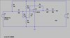
Hi all, I am a noobie here and am looking for help. I am trying to design a BJT Preamp for an ECM cartridge with which to test speakers. I use thru hole components and most of the designs out there require caps that are too big to get into the wand. So I came up with the following design that uses tiny caps and can be put into the wand. Yes it will fit into a 19 mm tube.

I have no training in this area so would like a review of my design and corrections and suggestions. Ideally, it would be great to have a design with reasonably low noise, decent distortion and wide bandwidth (down below 10 Hz). This is not a recording Mic so noise and distortion do not have to be vanishingly low. But lower is better. Also, gain should be such as to be able to get to 1V for line level inputs.

A condition that must be met is that I must use 12V DC to power the Pre.

R6 is a 10k Audio Taper pot in case things get too hot for Line In.

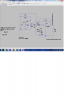
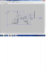
I have attached the schematic and the FR curve From LT Spice. The curve looks good with a low order rolloff and decent transient response on the low end. I would like the bass end extended an octave or so, but that is as good as I could do.

Could you all please take a look and critique what I have done? I do not know if my bias is set right, if the currents are ok for the application or if the gain is proper. I also have no idea about the inherent distortion of the design. Also I would like advice on R6, the Audio Taper Pot. I could go to 50K or 100K. What is the best here?

Any help or suggestions will be warmly appreciated.

Thanks.

Oh, one last thing, I do not know how to model an ECM in LTSpice so I simply used an AC signal source. I am sure that makes a difference, but it is all I could figure out to do.

Oh, one more last thing, I do not mind scraping my design entirely and go to a design with more transistors to get away from those emitter bypass caps. Of course I expect to keep the input and output caps and possibly some interstage signal caps. I was referred from a thread here to a thread about looking at Transistors as voltage controlled devices. There was a circuit there that by using two stages did away with the emitter cap. That is a wonderful idea, but way beyond my abilities. Hell, what I have posted here is way beyond my abilities. That is why I need help!

Exp Mic Pre FR.JPG

Exp Mic Pre Sch.JPG
 
Last edited:
It is exactly one of those WM61A capsule mics (calibrated) that I want to refurb. Got the message from SL many years ago.

Thanks for the reply
 
electrt amp

The one you have doesn't have much gain. Maybe an op amp like this?
 

Attachments

  • electret.png
    electret.png
    158.1 KB · Views: 333
All would be ok if I trusted the Mic capsule to faithfully pump its signal down 40ft of audio cable with an unknown spec for capacitance. But to be safe, a buffer or preamp should be in the mic wand up close to the capsule. Often suggested is an opamp that requires a dual supply. When using a bipolar supply there are not enough pins in a standard xlr jack/plug to do that. It is ok with phantom power because it is not bipolar. Three pins will do the job. So with a single ended supply the only choices are a ratty old single ended supply op amp or a BJT or FET circuit that needs only a single supply. That is my dilemma.

Also, I really don't understand the schematic you posted. My ignorance.

Suggestions?
 
What is the purpose of C2 ( in transistor version )?
It kills the feedback at higher frequencies and the waveform gets badly distorted.
You can check it in LTSpice, for example at 1000Hz.
 
hi ron,

This zip maybe helpful.

Eric
 

Attachments

  • micelectret1_test1.zip
    2.2 KB · Views: 163
BJT design form a voltage point of view

Hi,

In researching here I ran across some references and links to other sites about designing BJT circuits from a voltage point of view. But somehow I cannot find the links or references now.

In one of the references there was an example circuit that eliminated the typical NPN emitter resistor bypass cap by using an additional transistor.

Can someone please point me to that or other links that explain the process or shows circuits designed that way?

I am interested because I want to insert an ECM MIC Preamp into a MIC wand and cannot deal with the necessary large emitter bypass caps. My application requires the use of a unipolar supply so typical op amps are not a solution.

If you know of a circuit that will work (12V DC supply) please point me to it. I only need 10-20 dB or so of gain and an emitter follower output.

Perhaps a single supply op amp will work too. Any ideas?

Thanks for any help you can give.

I
 
What is the purpose of C2 ( in transistor version )?
It kills the feedback at higher frequencies and the waveform gets badly distorted.
You can check it in LTSpice, for example at 1000Hz.

I am no designer or engineer but I understand it provides for temperature stability. But it surely screws up the system unless it is very large. That is why I am trying to eliminate it. My application cannot physically have large caps in it.
 
hi ron,

This zip maybe helpful.

Eric

Hi, I am not ron. But Hi any way.

I found a one of the items in your zip file really interesting. It opens up in LTSpice as slick as can be. Unfortunately it has a really poor low freq response that would impair analysis of the designed system. I find the poor response quite interesting since ECMs are famous for their low freq response.

Thanks
 
Thanks Eric! I always wanted one of those.:D:D

Here is the scoop on the single supply op amp.

V1 is your 12 volt power supply.

C1, R1 is a power filter for the mic. Since with an electret the power supply noise gets passed thru to be amplified it is sometimes needed. If your power supply is real "clean" you can probably make C1 smaller.

R7 is the bias for the mic. The signal is developed across it.

R4 and R5 make what is called a virtual ground so a single supply op amp can be used. It just sets the voltage of the input half way between 12 volts and ground.

U2 is a pot to set the gain.

C2, R3 along with the feedback from the pot sets the gain.

U3 is Eric's microphone model.

Except for C1 the caps can be 10 volts.

I just built one like this for my remote speakers. It was a spaghetti design (no pcb) like yours will be I suspect. I had a little hummmm. So make sure to ground your tube. Hopefully it is metal.
 

Attachments

  • mic amp.png
    mic amp.png
    137.3 KB · Views: 261
Look at what was done by Linkwitz: https://www.linkwitzlab.com/sys_test.htm#Mic a lot of good info. E

Due to your post I decided to go back and analyze what Linkwitz presented years ago. It has given me new insight and a possible solution to my problem with some help from y'all. (I'm from florida!) thanks loads.

The new insight and some reading of TI app notes, etc. has me working on an op amp design. I will publish it shortly.
 
Last edited:
ronv,

Thanks for the schematic. I am working on a somewhat similar design as we speak. I took info from the TI app notes and the Linkwitz design (10 dB gain) and am gaining some ground. I will analyze your circuit as well. Hopefully you will be around for some help when I need it.

Thanks.
 
I am new to LTSpice. Only a couple days. With the info recently provided I have imported the MIC into a design but it is way bigger than the rest of the components supplied by LT. How do you shrink or expand individual components without expanding or shrinking all of them?

Thanks
 
I think you have to redraw it, but Eric is the expert. He will probably check in.
 
Well here is what I've got.

The Linkwitz ECM preamp circuit is the first image below. It is SL's circuit but I put the bias for the ECM is on the positive rail because I do not cut the ECMs. It is for a dual supply and here it is.

Link Sche.JPG

The FR for this circuit is below. It shows a gain of about 10 dB which is what his stated target was. Here it is.

Link FR.JPG

I followed the TI guidelines for single supply operation with OP Amps that are typically used with dual supplies (I have some nice ones). This type of circuit relies on a virtual or synthetic ground for the Op Amp's operation. The supplies to the Op Amp can be fed by a single supply as I show. But all circuitry relating to the operation of the Op Amp must be operated by reference to the virtual or synthetic ground. TI further says that since the supply ground is part of the system, that caps must be placed at input and output of the Op Amp's operations to safely and properly interface the Op Amp's input and output to single supply elements that do not reference the virtual ground. So, all operations within the caps must be referenced to the virtual or synthetic ground and elements outside the caps are referenced to PS ground. I have done that too. Here is the schematic.

My Sche.JPG

The bandwidth of my circuit is a bit better than the SL circuit because I used a bigger input cap. One thing that puzzles me is that I had to crank up the gain on the Op Amp to 20 dB in order to get 10 dB gain from input to output. Anybody know why? Does the virtual ground reduce the input signal? I can't figure it out. But here is the FR of my single supply circuit. Its not shabby and it is 10 dB gain from input to output.

My FR.JPG

A couple more things. There will be a .1uf ceramic between the Op Amp supply pins. If you know that the circuit output will go to a capacitor input, then I think the output cap can be eliminated. The likelihood is that all circuits that will interface with my setup will have capacitor inputs. The beauty of this circuit is that it is tiny with few caps and no big ones. It will easily fit into my 19 mm D pipe. And yes the pipe is metal and will be properly grounded. Now I must prevent ground loops.

One more thing, given the constraints suggested by TI, I am not sure the circuit provided by ronv will work properly. I have not put it into LTSpice yet (I was too busy with my own) but as I understand the circuit and TI's admonitions, R5 and R3 in ronv's circuit should be connected to virtual ground for single supply use. But in ronv's circuit it they are connected to actual ground. TI says no to that. Does the cap make the difference?

Please review my single supply version and tell me what is wrong with it or how to improve it and maybe tell me what is going on with the gain thing. All suggestions and objections are welcome.

Thanks
 

Attachments

  • My Sche.JPG
    My Sche.JPG
    32.6 KB · Views: 193
Last edited:
P.S. I took the time to sim ronv's schematic. Of course it did not work. What a waste of time. Why didn't someone warn me about him? This is the first time I have used the ignore feature in a forum.

hi,
ronv is a very helpful guy, I think your remark is out of line.

Good luck with your project.

E.

EDIT:
Decided to try 'ronv' simulation, it works as well as expected, I think you owe 'ronv' an apology.

If as you state, you are newcomer to LTSpice, I would suggest it would be better to ask for guidance if a circuit you are trying to run does not work.

E.
 

Attachments

  • AAesp02.gif
    AAesp02.gif
    55.5 KB · Views: 215
  • AAesp03.gif
    AAesp03.gif
    55.6 KB · Views: 196
Last edited:
Ronv, I apologize. Sorry, my ignorance again. My message is edited.

hi,
Your final circuit image has only a gain of about 3.

The problem is the OPA feedback resistor value [27k] is divided by the 5K and the three 10K's
in the biassing network. As you may know Gain = Rfeedback/Rin

I have run a test on the electomet microphone model of LTSpice and it matches close enough to the actual plot of a 'real' electomet.

The overlay drawing is not very clear, but you get the idea.

Eric
 

Attachments

  • AAesp10.gif
    AAesp10.gif
    48 KB · Views: 203
  • LTS_elect1.gif
    LTS_elect1.gif
    30.3 KB · Views: 183
No problem. :)

The 2 supply circuit works, but R3 should be larger. The reason is because the mic has a fairly high impedance. In the drawing shown it is 10K. To see the effects of this you can add 10K to the series resistance in the voltage source so you will loose 1/2 of the amplitude. It also needs a lot more gain if you want to get 1 volt out as the mic only outputs a few millivolts - maybe 5 in normal voice.
In the other circuits.. they just don't work well for several reasons but one is that they have DC gain. So If the input is at say 6 volts the dc will also be amplified. That is the purpose of the cap to ground in my schematic.. The DC gain is now 1 and the AC gain can be over 100. Here is the asc file so you can play with it. You can replace the TL081 with the LT1013 since you probably don't have the TL081 in your library. To run the bandwidth and stuff replace the mic with your voltage source and remove the 5K.

Maybe you could add the link to the TI sheet you are looking at. Maybe I'm missing something.
 

Attachments

  • electret amp.asc
    2.5 KB · Views: 137
Last edited:
Status
Not open for further replies.

Latest threads

Back
Top