Continue to Site

Welcome to our site!

Electro Tech is an online community (with over 170,000 members) who enjoy talking about and building electronic circuits, projects and gadgets. To participate you need to register. Registration is free. Click here to register now.

  • Welcome to our site! Electro Tech is an online community (with over 170,000 members) who enjoy talking about and building electronic circuits, projects and gadgets. To participate you need to register. Registration is free. Click here to register now.

bjt-hbridge

Status
Not open for further replies.

tonyke

New Member
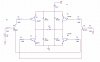
I am trying to set up a h-bridge circuit to control the TEC, no PMW.( In schematic I use the resistor instead.) I also used microcontroller to control the input of H-bridge with a DAC circuit connected to the microcontroller, and I have thermistor as feedback. The problem is how to add a switch circuit between the only output pin of DAC and the two pins of h-bridge. Or any analog device can do that. In h-bridge, one pin will be grounded and the other pin will be at certain voltage, which is controlled by the microcontroller. THX.:)
 

Attachments

  • hbridge.jpg
    hbridge.jpg
    235.2 KB · Views: 400
That bridge circuit is not designed for linear control, it's designed for switching a bipolar signal to a load. As designed the current would be a very nonlinear function of the DAC output voltage.

I don't understand why you are trying to use that circuit with a TEC. Are you trying to both heat and cool with the device?

And with a 0.5Ω load you will be dissipating up to 12W in the transistors which is a lot of wasted heat.
I agree with everything except the max power dissipation. Max transistor power is when Vce=Vcc/2.
Pmax=(Vcc/2)^2/0.5.
Pmax=72W. :eek:
 
Last edited:
Hi Carl
The 0.5ohm resistor is used to represent the TEC. TEC will change its resistance under different delta T.
You are right, it's not a linear circuit. I previously wanted the BJT to operate in linear region, but it's very difficult. But this circuit still owns unipolarity, and I have thermistor work as the feedback.
For the DAC and hbridge, I am considering to put an inverter before one side of the input. And adjust the dac output by summing Opamp. By doing that, I can adjust the input to TEC, for example, sth like -2.5V~2.5V.
 
I agree with everything except the max power dissipation. Max transistor power is when Vce=Vcc/2.
Pmax=(Vcc/2)^2/0.5.
Pmax=72W. :eek:
Yes, my mind somehow doubled the voltage rather than square it. Just a senior moment.:eek:
 
Hi Carl
The 0.5ohm resistor is used to represent the TEC. TEC will change its resistance under different delta T.
You are right, it's not a linear circuit. I previously wanted the BJT to operate in linear region, but it's very difficult. But this circuit still owns unipolarity, and I have thermistor work as the feedback.
For the DAC and hbridge, I am considering to put an inverter before one side of the input. And adjust the dac output by summing Opamp. By doing that, I can adjust the input to TEC, for example, sth like -2.5V~2.5V.
If you only need a unipolar signal, there's no need for the bridge.
 
no, i mean the unipolarity of the output with the input. I still need both cooling and heating.
Why you guys calculate the power dissipation like Pmax=(Vcc/2)^2/0.5? .5ohm is the resistance of resistor. why it is involved in the calculation of transistor?
the transistor should not consume much power in saturation because not too much voltage drop on that.
If the transistors are being used as switches then, yes, there dissipation will be low.

But you are mixing apples and oranges. You stated you want to drive it from a DAC output which would make it linear, not switching. If you want to just switch the bridge then you would use a digital output signal from the controller, not from a DAC. Just invert the digital signal to drive the opposite input on the bridge.

Got you. But why you said previously that the current would be nonlinear? I f the transistors are in active region Ic=hIb, thus I can control Ib to control the Ic. Why you say that it is nonlinear? Thanks.
 
Got you. But why you said previously that the current would be nonlinear? I f the transistors are in active region Ic=hIb, thus I can control Ib to control the Ic. Why you say that it is nonlinear? Thanks.
1. Small-signal h-parameters are not appropriate for large-signal amplifiers, because they are only constant for small-signal applications, and are actually nonlinear.
2. Beta (large-signal Hfe) varies over a WIDE range from unit-to-unit, and is not predictable enough to allow control of collector current in an open-loop amplifier.
 
Last edited:
For this application you should really go to a PWM type of signal to the bridge, if you want linear control. It simplifies the circuit and minimizes the power dissipation in the transistors.

If you insist on analog linear control, then you would need to go to an audio amp type of bridge which has feedback to linearize the output versus input.
 
I didn't use the PMW for the bridge because there will be much noise when using the switching mode. Do you think PMW mode is really linear?
 
I didn't use the PMW for the bridge because there will be much noise when using the switching mode. Do you think PMW mode is really linear?
Noise can be a problem, but you can suppress in with an LC filter at the output and careful layout of the circuit with a good ground plane and circuit decoupling. Keep the high frequency PWM signal paths as short as possible and away from sensitive points in the circuit.

PWM (not PMW) is linear in that you can generate a varying voltage output similar to a linear amp, but with much higher efficiency. The amount of linearity (input vs. output distortion) depends upon your requirements and the circuit design. Since this would be in a feedback circuit controlling a TEC, a high degree of linearity is not required.
 
Status
Not open for further replies.

Latest threads

New Articles From Microcontroller Tips

Back
Top