Continue to Site

Welcome to our site!

Electro Tech is an online community (with over 170,000 members) who enjoy talking about and building electronic circuits, projects and gadgets. To participate you need to register. Registration is free. Click here to register now.

  • Welcome to our site! Electro Tech is an online community (with over 170,000 members) who enjoy talking about and building electronic circuits, projects and gadgets. To participate you need to register. Registration is free. Click here to register now.

How to make AM radio transmitter with only BJTs

Status
Not open for further replies.

Fluffyboii

Active Member
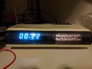
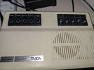
I found this beautiful clock/radio with turquoise vacuum display (it looks more blue on camera). It required the regular cleaning of pots and switches and for some reason someone didn't solder its speaker. Only problem now is that there are no good radios in range here. The antenna of this thing was cut so I soldered a new wire to make it longer but idk how long it should be, at least it gets better signal now. If someone can translate what switches mean it would be nice, for example what AUTO MANUAL or UHR and AUS mean. I pretty much figured the rest.

MW gets some radios with regular fiddling of the radio at 3AM but not as well as my ferrite core antenna radio.
This really made me want to make a simple AM radio and play my own music on it. My school has many powerful transistors in its storage that I can use like bc140, bc160, there are also very overpowered transistors with metal casing that acts like one of the connections. It is really stupid that they got those very expensive BJTs but didn't get any comparators, 555 ICs and other simple stuff that students often need.

The thing is I accidentally made the required components of an radio for my modular synth with op amps. They wont work at high frequencies but fun to play with for making music. I also have a vague idea of what I need to make one from my analog/digital communication class. I need a pure sine wave fed to a voltage controlled amplifier that is biased with some DC voltage so that it can be demodulated with a simple diode envelope.

I could probably use a simple op amp amplifier for sound input stage and add a electret mic for fun but I am really in the mood of torturing myself with analog circuit design. I want to make something I can show to my teachers with pride that only consists transistors soldered on a piece of copper like how old electronics predating PCBs were put together.
I was looking at different circuit designs for simple AM radios. Most of them are using base of a BJT to modulate the signal by changing the collector current and a simple RC circuit to determine the operating frequency. Or there are circuits that I don't understand anything about because they are hella complex.

For sound input stage I think I can get away with a simple CS amplifier and a source follower to amplify the input since I don't need to much gain and I don't think inverted signal will prove any problems. The confusing thing is getting a pure sine wave with a fixed frequency. I was thinking of using a quartz crystal but smallest I can get is 2Mhz and even if I use a clock divider I don't think it is wise to use 1Mhz and I should use a less used frequency at the edges of MW radio frequencies. There was a LM13700 triangle to sine shaper circuit I made for an LFO but even though sine wave out of that thing looked nice I don't think it can operate in Mhz range. Looks like I need to use a simple BJT RC oscillator. Single transistor ones seems a bit unreliable so I will need to look into it. I also need to figure out a way to make a transistor VCA. This one is nice but idk how to make it without op amps since its is using one to subtract voltages and it probably doesn't work with negative CV inputs. One way I know to make a multiplier is the simple 2 transformer, 4 diode textbook sample but those transformers are expensive and hard to deal with in audio frequency range and I expect non the less for AM range.
1669645629235.png

Before jumping to say transmitting radio signals are illegal, I know. As I said there are no AM radios here that can be heard with even the best radio I could find in daytime. At the middle of the night I can find some Russian or Greek radios and thats it. And I also know that doesn't change the fact that this thing can create interference and alarm some authorities. All I want to make a nice transmitter that can be scaled up and doesn't use sketchy techniques to keep part number or complexity low and learn a bit more about radio transmission stuff. I will eventually figure it out myself by checking old radio books and textbooks. I think if I can make something nice it would at least not create unnecessary interference and it is not like I will transmit radio 7/24.
 

Attachments

  • IMG_20221128_002239.jpg
    IMG_20221128_002239.jpg
    387.6 KB · Views: 192
  • IMG_20221128_003026.jpg
    IMG_20221128_003026.jpg
    499.6 KB · Views: 192
Last edited:
If someone can translate what switches mean it would be nice,
SCHNELL = Fast
LANGSAM = Slow
SCHLAF = Sleep
ALARM AUS = Alarm Off

SEK = Seconds
ZEIT = Time
UHR = Clock
AUS = Off
UKW = Ultra Kurz Welle = Ultra Short Wave = VHF
AUTO = Automatic (Clock turn the radio on)
MANU = Manual (This switch position turns the radio on)


As for building an AM transmitter, you may like to start with a simple oscillator which produces a signal at about 1MHz.
Have a look at my posts in this ancient thread:

JimB
 

Attachments

  • vdocuments.net_-the-best-qrp-projects-from-qst-and-the-arrl-handbook.pdf
    31.2 MB · Views: 178
If you are transmitting to a MW receiver less than a metre away, you will only need microwatts of power.

When I had a car with a LW receiver, I could receive a broadcast signal from 600 km away. That was transmitting at 750 kW.

If you are less than a metre away, that is 600,000 times closer than I am to that transmitter. According to the inverse-square law (https://en.wikipedia.org/wiki/Inverse-square_law), to get the same signal intensity, you would need to transmit at around 2 microwatts.

There are a few reasons why the inverse square law isn't accurate in this situation, but 1 mW or so would be plenty if you are transmitting to a receiver close by.

However, I would find the volume control, disconnect whatever is connected to the clockwise end of that, and feed an audio signal of my choice into that end of the volume control. It would take a lot less effort, and there's far less risk of inadvertently transmitting something that others could be upset by.
 
However, I would find the volume control, disconnect whatever is connected to the clockwise end of that, and feed an audio signal of my choice into that end of the volume control. It would take a lot less effort, and there's far less risk of inadvertently transmitting something that others could be upset by.
This makes a lot of sense for using custom music playing for alarm. Possibly I could get the "radio on" signal from the radio light and use it to start playing the music as soon as the radio turns on as alarm so that I don't need to constantly play music until it turns on. But honestly I don't think I will use this clock all the time since the display in it is probably doesn't last as long as its LED counterparts and impossible to find a replacement. I taped over its LDR that turns the brightness up when ambient is lit up so that it stays dim all the time and takes less toll on the display. It is unfortunate that there is no option to turn the display off and on for checking the time but guess that wouldn't make sense for this type of clock.

For my AM experiment I am planning on using a Colpitts oscillator and a Gillbert cell made out of transistors as modulator. However it seems that Gillbert cell has some weird limitations like signals needing to be under Vt. I will try to simulate both in LTSpice and try to prototype it on copper when I have free time.
 
AM radio has AMplitude interference clicks and pops and maybe two or 3 stations can be heard at the same time.
AM radio has a narrow bandwidth that cuts all high audio frequencies so music sounds muffled, and speech has all the important high frequency consonant sounds removed reducing the understanding of many words.

It looks like your clock radio is very old and has a little 3" speaker that produces no low frequencies and no high frequencies. Its fluorescent display might not last long.

I bought two modern clock radios at a discounts store for a very low price. I tried one on FM and its little 3" speaker sounded awful producing low maximum volume and no high or low frequencies. Inside its amplifier circuit had 3 low value coupling capacitors that I uncreased so that low frequencies can be produced on a good speaker. I disconnected its junk little 3" speaker and replaced it with an external 2-way speaker I made with a 6.5" woofer, a dome tweeter and a crossover network in a ported fairly large enclosure.

Now it plays the FM radio perfectly with good bass and good high frequencies. It has very low distortion even when playing much louder than originally. I never listen to the muffled AM radio.
Pretty much spot on. What uncreasing capacitors mean though. Is it the cutting parts of small ceramic caps to decrease its capacitance thing I heard years ago. The unwanted AM interference and harmomics invading other frequencies can not be fully prevented I guess. I always read about bandwith issues with DSB and how they were coping with SSB and other methods and difficulty of having sycnronised oscillators but never understood how bandwidth effected the signal considering it is just Amplitude modulated and unless they used transformers to make a modulators, with high bandwidth of BJTs and Mosfets it shouldn't have thouble. Is it the envelope detector thats cutting the top and low ends dying because I don't really think any other way why bandwidth would be concerning in these systems.
One reason I wanted to make a AM transmitter for a while was to put the concepts they have been pushing on me for some time for some kind of use and no one would care since it is pretty much dead.
I should have a FM transmitter I build years ago and failed to make it work because I killed one of the transistors but the shop owner gifted me another pre made one when I was first interested in electronics. It wouldn't be hard to just solder a dc adapter to it. This clock is cheaply made inside, I am assuming it is not too old since it got a single IC doing all the clock work. My guess is 1980's after seeing similar units online. The fluorescent display concerns me but it gets really bright when light hits its sensor so I think its doesn't have too many hours on it. I will probably not use it too much to preserve the thing but except its volume pot's persisting oxidation causing it to made crack sounds at low volume levels even though I poured a lot of iso on it it sounds nice and gets suprisingly loud.
 
Last edited:
Most of us can hear frequencies from 20Hz to 20kHz. AM radio stations are only 10kHz apart so to reduce adjacent frequency interference an AM radio bandwidth is up to only about 3kHz, like an old telephone.

The capacitance of the audio coupling capacitors in the amplifier circuit are too small because the cheap tiny speaker in a clock radio is too small to produce low frequencies.
1) If an audio amplifier has a 10k ohms input resistance then a 1uF capacitor is calculated to pass all frequencies down to 16Hz.
2) 0.1uF cuts most bass frequencies below 160Hz to the 10k ohms amplifier input.
3) Most speakers are 8 ohms. If the coupling capacitor to it is 1000uF then all audio frequencies down to 20Hz are passed to the speaker.
4) A 100uF capacitor cuts all bass frequencies below 200Hz to an 8 ohms speaker.
5) Many amplifiers have a (third) capacitor to ground in the negative feedback.
 
Most of us can hear frequencies from 20Hz to 20kHz. AM radio stations are only 10kHz apart so to reduce adjacent frequency interference an AM radio bandwidth is up to only about 3kHz, like an old telephone.
Never thought that way because how tightly radio stations are packed in FM. I read people thought FM would solve high bandwidth issues but it wasn't any better so how can they get away with putting them that close. In fact I can't even listen to some channels on old radios without signal getting mixed with others. Also FM litteraly changes frequeny with signal so how can receiver track it idk. Will learn as comms. class moves on I guess.
 
There are a few FM detectors that work perfectly and a few cheap or old FM detectors that perform very poorly and actually use an AM detector which you noticed.

FM radio stations play audio frequencies from 50Hz to 15kHz, a 19kHz stereo pilot tone, stereo sidebands from 23kHz to 53kHz and sometimes SCA storecast music or text of what is playing plus an ad for the station.
The station's bandwidth is about 100kHz and the station frequencies are spaced 200kHz apart.
An FM radio has "Capture Effect" so that if two transmitters are received on the same radio frequency, only the stronger one is heard. That would cause disasters if airplanes used FM for communications because then many "Mayday" calls would not be heard.

If two AM stations on the same radio frequency are received at the same time then they are both heard mixed together as you noticed on an old FM radio.
 
1669729855874.png

Can someone explain me the multiplier part of this. It changing current mirror total current with the bottom transistor and feeds the carrier to left transistor. But this should be only a 2 quadrant multiplier and shouldn't be able to used for AM modulation. For AM modulation shouldn't a Gillbert cell used lite the one at the bottom. Or does it not matter because the AC signal is superimposed on BJT bias voltage and total input voltage never goes below 0. And why a LC tank circuit is used at the antenna side.
1669729990593.png
 
The modulation input varies the long tail pair standing bias current.

So, the available current range through the output transistor varies with the modulation level.
Different current range means different voltage swing across the output load, and different power.
The LC circuit provides some filtering and improves the match to the antenna circuit.

In many simple AM transmitters, the power supply to the output stage is simply coupled via a transformer winding, with the modulation applied to the other transformer winding. That varies the voltage to the PA up and down in accord with the modulation input.

They are fundamentally very simple devices.
 
An LC tank is used at the antenna output to reduce interference transmitted at harmonic frequencies caused by transistors distortion.
 
Only a pair of transistor can only produce a 2 quadrant multiplier.

A four quadrant multiplier takes many more transistors. 2 Quadrant is enough form AM
From my understanding as long as I am not gonna do DSB-SC and just normal AM it is as you said fine to use a current mirror set up like that. Will try making a oscillator and multiplier out of transistors and see if I can check it with my oscilloscope.
 
From my understanding as long as I am not gonna do DSB-SC and just normal AM it is as you said fine to use a current mirror set up like that. Will try making a oscillator and multiplier out of transistors and see if I can check it with my oscilloscope.
Why are you making it complicated? - post #13 gives you some actual practical amplitude modulator examples.
 
Why are you making it complicated? - post #13 gives you some actual practical amplitude modulator examples.
I don't fully understand the first one. And the second one requires me to wind a transformer. I want to keep copper wound things at minimum to make it easier to build. First one is ideal for that but I need to figure how it works. Trying to make and tune one myself is more difficult than using one of those but I can make parts seperated and try to merge them together later.
 
I don't fully understand the first one. And the second one requires me to wind a transformer. I want to keep copper wound things at minimum to make it easier to build. First one is ideal for that but I need to figure how it works. Trying to make and tune one myself is more difficult than using one of those but I can make parts seperated and try to merge them together later.
For a transmitter you NEED!!! a transformer, or at least wound coils for tuned circuits - the first of those two examples is truly horrible, and would cause massive interference all over the RF spectrum - and appears to be designed to do just that.

Just as a receiver needs tuned cicuits, so does a transmitter.
 
I don't fully understand the first one. And the second one requires me to wind a transformer.
They both work by the audio modulation varying the supply voltage to the output stage.

The first should be more stable as the oscillator is separate. Also, the values in the second one are for short wave bands, not medium wave; the inductor values would need recalculating. I included that as an example of simple modulation.
 
Status
Not open for further replies.

Latest threads

New Articles From Microcontroller Tips

Back
Top