Continue to Site

Welcome to our site!

Electro Tech is an online community (with over 170,000 members) who enjoy talking about and building electronic circuits, projects and gadgets. To participate you need to register. Registration is free. Click here to register now.

  • Welcome to our site! Electro Tech is an online community (with over 170,000 members) who enjoy talking about and building electronic circuits, projects and gadgets. To participate you need to register. Registration is free. Click here to register now.

Bipolar return-to-zero modulation

Status
Not open for further replies.

Savlon

New Member
Hi all...
Im trying to create a cct that will allow me to use a PIC microcontroller to transfer data complient to ARINC-429 aviation standard. This standard uses bipolar return-to-zero modulation for data transfer.

Basically you have two wires for transmitting data, for a logic '1' to be transmitted one wire is to be +5V and the other to be at -5V followed by a null state (return to zero). I have included an attachment with a diagram of this.

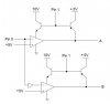
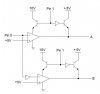
What i need is to create a circuit that will allow me to apply +-5V and 0V onto the two wires. I have come up with a rough idea of a cct, any comments/tips/help would be much appreciated.

In my diagram i have used Pin0 to determine the '1' and '0', and Pin1 to supply 5V for the null value.

Cheers
Liam
 

Attachments

  • BPRZ.JPG
    BPRZ.JPG
    20.8 KB · Views: 794
  • cct1.JPG
    cct1.JPG
    18.7 KB · Views: 797
Oops think i made a mistake with the PNP transistors, i'v replaced them with NPN and used a NOT gate instead. So when Pin1 is low, the output on A & B will be null. When Pin0 is high the output depends on the status of Pin0.
 

Attachments

  • cct1_126.jpg
    cct1_126.jpg
    19 KB · Views: 672
I don't understand your symbols, but it appears that you are using +10, +5 and GND to simulate +5, GND, -5. This circuit uses a voltage inverter, MAX1681, to generate -5v.
 

Attachments

  • DATA_CONVERTER.jpg
    DATA_CONVERTER.jpg
    36 KB · Views: 631
Can you not just use a ARINC 429 Line Driver? its much easier and will handle the rise and fall timings for you so that they adhere to the ARINC specification (1.5uS+/- 0.5uS if I remember correctly for High speed 100Kbits/second). The pulse timings will be controlled by your input pulse from a uController.

Try HOLT Integrated Circuits, **broken link removed** , you never know you might be able to manage a sample for a prototype.

I work with ARINC regularly and use the HI8585, without any problems, all the time.

It depends what you are planning on talking to, but some ARINC receivers can be very awkward when it comes to the receiving signal being within specification, so your best option probably is a Line driver IC.

ARINC Tutorial - www.condoreng.com/support/downloads/tutorials/ARINCTutorial.PDF
 
Thanks for the info geordie, i never new there was a device that did this kinda stuff (well i presumed there would be but couldnt find one, guess i didnt use the right keywords in my search). I'll have a look into one of those line drivers.

Cheers again!
 
Hi geordie, how do i know whether the data communication is going to be at its high speed rate or low speed (100kbs or 12.5kbs)? is this something i would have to ask condor?

Does it depend on which version of the Bit-oriented-protocol i use?
 
It depends on your application, what do you want to send data to?

If you are only transmitting to an existing system, see what it uses, either from its specification or experiment with both. If you are going to create your own receiver then all you have to do is match the two.

I work with aircraft systems that use the high speed system, but many of the line drivers and receivers we use are capable of both with very little difference in the support circuitry.
 
Im designing a black box for my university project, and i want it to be able to receive GPS information from the com bus. I'll need to transmit and receive because of the (annoying) Williamsburg Protocol :D

I'll give Condor an email n ask them. Unfortunately i dont think i'll be able to connect the box to the bus if the GPS transmits at the high speed as my hardware isnt fast enough (and its too near deadlines to change my design). Maybe im a bit too ambitous for my first project iv done on my own :oops:

Thanks for your reply!
 
The important thing now in terms of your project is to decide if there is a way you can fix it so that it works, if not, I suggest you consider why it hasn't worked and what you could have done about it if you started from scratch.

Most university projects, its not about if you implement it, its about what you learn while trying (corny I know, but thats the way it is) if you can provide a good enough breakdown of why you couldn't implement the hardware/software and what you would do instead if you had to do it again, you should be able to get similar marks to those that you would have if you completed it.

Look at the mark breakdown, generally little of it is for the final part working.
 
Status
Not open for further replies.

Latest threads

Back
Top