Continue to Site

Welcome to our site!

Electro Tech is an online community (with over 170,000 members) who enjoy talking about and building electronic circuits, projects and gadgets. To participate you need to register. Registration is free. Click here to register now.

  • Welcome to our site! Electro Tech is an online community (with over 170,000 members) who enjoy talking about and building electronic circuits, projects and gadgets. To participate you need to register. Registration is free. Click here to register now.

Binary Clock

Status
Not open for further replies.
Finally Here!

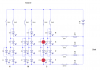
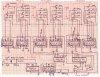
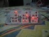
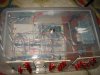
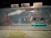
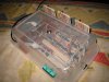
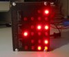
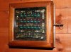
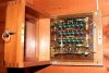
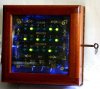
Ok, It took QUITE a while but it's finished.

I know it looks like your granny's old (and I'm not talking about the case only) but TTL gates and that sort of stuff is all the technology I know so far.

Sure someone can pull this one out in micros (or something more advanced) but not me, not until next semester at least!

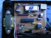
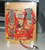
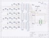
It takes a while to assemble and you need extreme care so that you don't mix up any connection...

And DON'T take a leaf out of my book, I only passed wires over the ICs because the cables already cut were like that on my protoboard and I had no time for measuring, cutting and stripping new ones!

I'll be watching this topic so... any questions just post!
 

Attachments

  • binclock.jpg
    binclock.jpg
    196.9 KB · Views: 2,547
  • img_2667.jpg
    img_2667.jpg
    195 KB · Views: 2,304
More Pics...

More pictures...

Notice I added an additional switch that turns off all the leds (except the inner one that blinks every second) just in case you can't sleep with all that mute rave on your room. (Obviously time keeps running while lights are off).

I usually like the back-to-the-future see-trhu look so don't go on thinking that I was short on cash and raided the kitchen. This is brand new tupperware technology! :lol:
 

Attachments

  • top_948.jpg
    top_948.jpg
    103.5 KB · Views: 2,186
  • adjust.jpg
    adjust.jpg
    76.4 KB · Views: 2,269
  • switch_546.jpg
    switch_546.jpg
    112.2 KB · Views: 2,175
Last one

And many thanks to the people from tupperware and the duct tape that holded it all there for me wile I worked...
 

Attachments

  • side.jpg
    side.jpg
    67.2 KB · Views: 2,149
Important!

***Don't overlook this!***

Notice there is one 7490 among those 7993's
I couldn't figure out another way for the last "digit" to be reset when it needed to. :?:
So I included a decade counter (not a four bit counter like the others). 7493 counts to 16 (15 actually) but 7490 is reset in 9. (That's right is it not?)

And also check this: 4060 is CMOS technology so be careful you don't want to zap it while handling I even used a IC socket so that I didn't have to solder teh IC itself.

In case you're wondering, the 7486 is an XOR gate, I'd explain what I used it for but that would be an awful lesson of logic systems coming from me... I'll just leave it on: It helps you adjust the time without interfering with the clock running on its own.
And the 74279 is a latch used to make a bounceless switch (I think that's what it's called) so that the time advances only one minute or hour for every time you press the button (it would go two or three, several times en every push because of the mechanical oscillation that occurs when you push it...)

Last of all, notice those switches are momentary SPDT.

Let me know of any comment (not concerning the technology used, for I already said that I know it could have been better and more power-effective and smaller, but not with my science, I haven't gone so far yet... maybe next year).
And if you build one post some pictures for us!

Good Luck!

"The cure for boredom is curiosity;
there is no cure for curiosity".
- Ellen Par -
 
Reading it

It's BCD (Binary Coded Decimal)

Every column is a decimal digit, so you have six columns as the digits in your common digital clock (with seconds), the hours on the left and seconds on the right obviously...

And in every "digit" the lights represent the bits, on=1, off=0. The MSB on top, the LSB on the bottom (i.e. Most and Least Significant Bit).

e.g. 2004
Most significant digit: 2
Least significant digit: 4
So you read every column from the top, like:
2
0
0
4

In case someone doesn't know how to read binary:
multiply the LSB by 1 and add:
the multiplication of the next bit by 2 and add:
the multiplication of the next bit by 4 and add:
the multiplication of the next bit by 8 and add:
the multiplication of the next bit by 16 and add:
the multiplication of the next bit by 32 and add:
the multiplication of the next bit by 64 etc.

That is: bit x 2^number of bit (right-most is 0 zero)

So:
100101
is:
(1x2^5)+(0x2^4)+(0x2^3)+(1x2^2)+(0x2^1)+(1x2^0)=
(1x32)+(0x16)+(0x8)+(1x4)+(0x2)+(1x1)=37

So the clock on the image where you can see the leds on reads:
08:15:13
:arrow: thanks to mechie for the correction, it should read: 08:15:23

Hope I made myself clear...

Good luck again!
 
Binary Clock project

LApprenti Sorcier said:
So the clock on the image where you can see the leds on reads:
08:15:13

08:15.23 ?

This is excellent! I love to see someone taking an idea and sticking with it to completion, the photos really make a difference in understanding what you have achieved.
As for your method of construction, I see nothing wrong with it - I prefer to get a project working first and 'pretty' later (if at all !), wires jumping over ICs add to the drama, a neat printed circuit board makes things look much simpler (less scary for people not 'in the hobby').
(attached photo of one of my NEATEST projects (a tuning aid built into a radio for a friend who builds little hand-turned organs - the radio still works!)
... NOT ATTACHED - problems with website ? ... still trying

The Tupperware box idea is interesting, a kitchen-themed clock :?:
How about building the same clock into the base of a bedside lamp as the power lead is already there, one item with two functions :?
 

Attachments

  • main_board.jpg
    main_board.jpg
    413.1 KB · Views: 2,123
errata

My mistake,

Mechie is right, it is 08:15.23

I thought I'd made at least a mistake with all that...

:!: Hey, I like the bedside lamp idea!

Thanks!
 
hmmm...tupperware containers as project boxes

I think my mom is going to get mad when her tupperware starts disappearing...

good job though.
 
:lol: Of course!

I've used tupperware for everyting!

I even have a lunchbox 5V power supply.

Really handy LOL

Just don't tell your mom who gave you the idea...

:wink:
 
I was interested in making a binary clock and this is what i ended up with. I does not track time as good as it could because i ran out of time and interest at the end. I loses about 2 minutes everyday, but is fun to watch. I built it using a 16f628, (3) 57ls373's and a few resistors. The top 2 rows show the hour in bcd 24HR format and the 2 middle rows show the minutes and last 2 rows show the seconds.

Enjoy reading this board

David
 

Attachments

  • binclock1.jpg
    binclock1.jpg
    49.7 KB · Views: 1,407
  • binclock3.jpg
    binclock3.jpg
    38.9 KB · Views: 1,495
It's very nice! (And it doesn't take up the space of the refrigerator!)

Time base is no problem, really, just a couple extra components... (Check the bottom-left part of my schematic)

I'd be very interested in seeing your schematic if you have it and are willing to share it.

Greetings!
 
Bianry Clock

Sorry, I couldn't get a good scan of my printout, and I can't seem to find my original file. I have included the assembly also.

David

BinaryClock.asm
-------------------------------
time equ 0x30
sec equ 0x31
min equ 0x32
hour equ 0x33
xxx equ 0x34
ooo equ 0x35
cntr equ 0x36
cntr2 equ 0x37
cntr3 equ 0x38

org 0x00
goto start


start CLRF PORTA ; Initialize port A
BSF STATUS,RP0 ; RAM bank 1
movlw 0x08
movwf TRISA ; 3 input
movlw 0x80
movwf TRISB ;7 input
BCF STATUS,RP0 ; RAM bank 0
MOVLW 0x07
MOVWF CMCON
movlw 0x01
movwf sec
addlw 1
movwf min
addlw 1
movwf hour
bcf xxx, 0
bcf xxx, 1

main call set
call show
goto main


set btfsc portb, 7
goto out3
call delay
btfsc portb, 7
goto out3
call delay
incf min, 1
call show

out3 return


show movf min, 0
movwf portb
bsf porta, 1
bcf porta, 1
bsf porta, 1
bcf porta, 1
clrf portb
return


delay movlw 0x08
movwf cntr
delay1 movlw 0x80
movwf cntr2
delay2 movlw 0x80
movwf cntr3
delay3 decfsz cntr3,1
goto delay3
decfsz cntr2,1
goto delay2
decfsz cntr, 1
goto delay1
clrw
return
 

Attachments

  • scan0002.jpg
    scan0002.jpg
    81.7 KB · Views: 1,474
This topics a bit old now but here's a few pics of a binary clock I built a few years back.

The display is on sheet of clear plastic sheet. The main cct board is mounted behind and is lit by blue LEDs. The wooden box has a glass front so the wiring and components can be seen fron the front.
Brett.
 

Attachments

  • img_1447.jpg
    img_1447.jpg
    19.6 KB · Views: 1,097
  • img_1448.jpg
    img_1448.jpg
    19.2 KB · Views: 1,102
  • bcd.jpg
    bcd.jpg
    29.3 KB · Views: 1,036
Desktop Binary Clock

Here's a link to my windows binary clock **broken link removed**

Its only a tiny file about 100k. It does not need installing just run the single file from where ever you extract it to.

This is made to simulate my ideal binary clock using 7 segment displays rather than leds. This may be a bit expensive to build in real life!
Brett.
 

Attachments

  • bcd_big.jpg
    bcd_big.jpg
    32.6 KB · Views: 1,125
Very nice projects guys! I think I might just try to build one 8)

oliverb, what if,instead of 0s and 1s, it were bi-color LEDs, or simply dim a red LED for 0s, and bright for 1s? It'd be a whole lot cheaper, and just as cool in my opinion using your layout ;) 8)
 
what if,instead of 0s and 1s, it were bi-color LEDs

This is a good idea as in a dimly lit room it is hard to see the "0s" using LEDs. This is 1 of the reasons why I have a backlight in my LED binary clock.

Brett.
 
In the above sruger's circuit, the idea of using 3 additional ICs, 3 resistor packs and all the wirings for driving LEDs seems strange to me as we are using a PIC here. It can do the job perfectly all by itself.

Just arrange the LEDs in a matrix and scan the row using the port lines. With only a max of three LEDs ON at a time the 20mA pin current output of the PIC can easily drive high efficiency RED LEDs without the need of extra transistors. One therefore needs only 4 resistors for all the LEDs.

There you go. A working binary clock using a PIC, a 4MHz crystal, LEDs and a few capacitors and resistors. Don't forget to add push button for adjusting the time.
 
eblc1388 said:
In the above sruger's circuit, the idea of using 3 additional ICs, 3 resistor packs and all the wirings for driving LEDs seems strange to me as we are using a PIC here. It can do the job perfectly all by itself.

Yes, I was surprised to see so much components on what seems to be a pretty simple PIC project. But if it works...

It just goes to show that some of us are more comfortable in software and others in hardware. The best of us have probably learned when to use both together efficiently...
 
See attached schematic. It is roughly what eblc described, or at least that's what I was aiming for ;)

Each SPST switch represents a PIC port pin. I used resistor values to let ~7mA flow through each LED, so that I don't need transistors.

Now, is there an easy way to get dimmed LEDs for zeros? I tried a lot of ways, but it's probably out of my reach for now, because I ended up with blown LEDs, blown resistors, or randomly lit LEDs at every attempt I made. I initially thought that using the right resistor values to kind of "bypass" each switch would do it... it's probably not that easy. Am I at least on the right track?
 

Attachments

  • binclock_184.png
    binclock_184.png
    13.1 KB · Views: 1,063
Status
Not open for further replies.

Latest threads

New Articles From Microcontroller Tips

Back
Top