Electro Tech is an online community (with over 170,000 members) who enjoy talking about and building electronic circuits, projects and gadgets. To participate you need to register. Registration is free. Click here to register now.
Welcome to our site! Electro Tech is an online community (with over 170,000 members) who enjoy talking about and building electronic circuits, projects and gadgets. To participate you need to register. Registration is free. Click here to register now.
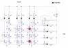
The port pins can only switch to HIGH or LOW, so I amended the circuit.
If you want a dim LED, you can consider adding high value resistors(only one shown in drawing) directly bypassing the PIC control resulted in dimly lit LEDs . See circuit.
For now my hardwork is limited to the above circuit But I promise to post pictures to this thread when I get some soldering done. In fact, I'd like to document the whole process on my website, from my first post here, to a complete schematic, step-by-step picture walkthrough, down to the actual woodworking involved in the enclosure fabrication We'll see if I manage to get it done...
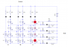
I've had an idea using Bi Colour LEDs. See pic normally the Gn Led would light showing 0. When S6&7 close the Red led would light and Gn would go OFF due to the higher forward voltage of the Gn LED showing 1.
I pesume you could reverse this by swapping LED connections and adding series diodes on the Red Led.
Nice. I'm not sure which idea I prefer, dim & bright or bi-color. I'm affraid 2 colors would be hard to read?... unless the 0 (green) is made a little dimmer and the 1 (red) brighter?
I've had an idea using Bi Colour LEDs. See pic normally the Gn Led would light showing 0. When S6&7 close the Red led would light and Gn would go OFF due to the higher forward voltage of the Gn LED showing
Interesting idea of using the slightly lower forward voltage of red LED to turn off green LED.
Only one problem though, those bi-color LED never exists. :shock:
You have made separate connection to all four legs of the bi-color LED but the actual one I have seen all have the common cathode connected internally(3 legs) or connected back-to-back(2-legs).
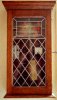
Here a pic of a Pendulem controlled Binary clock I built around 20 years ago. This clock had a half second pendulem that operated a change over contact once a second.
The clock is around 2ft tall and is wall mounted.
The pendulem was energised by a hip togle switch every 14 seconds.
The binary clock drive was connected to the change over contact by a noiseless switch.
Brett.
This site uses cookies to help personalise content, tailor your experience and to keep you logged in if you register.
By continuing to use this site, you are consenting to our use of cookies.

")
 We'll see if I manage to get it done...
 You are right the LEDs only have 3 legs this would only work with 1 sw.
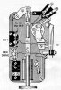
")