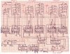
I have built the binary clock from the attached schematic. On my breadboard, it worked great, but after transferring to a pc board, the minutes trigger at 40 seconds instead of 60. The binary counters work as they should...everything seems ok except for that one thing. I have checked my wiring over and over and cannot find any mistakes. Any ideas?
Thanks so much for your time!
Thanks so much for your time!