Continue to Site

Welcome to our site!

Electro Tech is an online community (with over 170,000 members) who enjoy talking about and building electronic circuits, projects and gadgets. To participate you need to register. Registration is free. Click here to register now.

  • Welcome to our site! Electro Tech is an online community (with over 170,000 members) who enjoy talking about and building electronic circuits, projects and gadgets. To participate you need to register. Registration is free. Click here to register now.

biasing question

Status
Not open for further replies.
You don't have a heatsink. You just have a little piece of metal that might dissipate only 5W max. A real heatsink is extruded aluminum, is big and has many fins for a high surface area.
Maybe excessive heat has damaged the output transistors and T3.

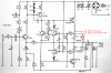
How are you measuring the current in the output transistors? You must measure the voltage across the 0.34 ohm emitter resistors then use Ohm's Law to calculate the current.

Where did you get the antique parts for that old circuit? The output transistors are darlingtons. If you substituted ordinary transistors then the current will be very high.

Did you substitute any other parts?
Is it built on a pcb? A breadboard cannot correctly pass the high currents.
 

Attachments

  • Amp.png
    Amp.png
    344.9 KB · Views: 132
Audioguru, you got me concerned there for a moment when you asked about the replacement transistors I use. I thought I had made a mistake.

I put a TIP 142/147 pair in as replacement, and I guess that would be ok.

The amp works fine if I do not crank up the quiescent current (and yes, as you guessed I measure the voltage over the emitter resistors). Once I try to get that up to specs (which call for 170 -200 mV being indicative of 50mA the spec sheet says) the unit heats up. I took these values at face value, but when I calculate them myself I end up with a base current of ten times what was given in the specs. Am I right here???

That would put 28 Watt into my "heat sink" during idle and would explain why I can fry eggs on it.

And yes, to answer your last question, the whole thing is built on a decent pcb.

So what is the importance of the quiescent current and what value should it have??

Uwe
 
The quiescent current is to prevent crossover distortion, if you turn it down to zero, and input a very low level sinewave you will be able to see it on the output. You can then increase the quiescent current until the crossover distortion disappears.
 
The emitter resistor is 0.34 ohms. 200mV across it is 588mA! 50mA is only 17mV.
Post a link to the project so we can see why there is the error.

28W is not much heat for a 42W amplifier. The heatsink should be big enough so that it doesn't get hot enough to fry eggs or destroy transistors.
 
The error is that I took the scant info I have with this amp, including the voltage drop over the emitter resistors, without going over the calculations and the values were off by a factor of ten!

That all by itself does not distroy anything, but together with the "thermal bar" (you pointed out that this could not be considered a heat sink and would have to be augmented for full output use) cranks up the heat to a near breaking point.

Now everything runs nice and cool.

The quiescent current which I set at around 17 mV wanders around a bit under use, after a few minutes of loud music it inches up with the slightly elevated temperature of the "heat bar", I guess this is due to not perfect tracking of T3 (BD139) . As the temperature goes down again so does the current.

Uwe
 
Good, now the amplifier is class-AB instead of nearly class-A.

I heard a new song on the radio that will probably overheat your amplifier. Its bass is nearly continuously at full power.
 
Well, a long time passed and I have a few of these amps running, but every now and then I come across one which gives me problems adjusting the bias of T1.

Right now I have one amp partially built, basically only T1 with its biasing circuit, and I cannot get the voltage at the base adjusted, with P1, to get a clean output at the collector of T1, it is clipping badly even with a -20dB input sine wave.

The voltage at the base is in excess of 40 volt with a supply voltage of 68 volts, and whenever I adjust P1 the base voltage slowly drifts back to the 40+ voltage.

Why??

Uwe
 
Othello said:
Well, a long time passed and I have a few of these amps running, but every now and then I come across one which gives me problems adjusting the bias of T1.

Right now I have one amp partially built, basically only T1 with its biasing circuit, and I cannot get the voltage at the base adjusted, with P1, to get a clean output at the collector of T1, it is clipping badly even with a -20dB input sine wave.

The voltage at the base is in excess of 40 volt with a supply voltage of 68 volts, and whenever I adjust P1 the base voltage slowly drifts back to the 40+ voltage.

Why??

Uwe
With 68V, the minimum you should expect at the base of T1 (ignoring base current) is about 41V.
Regarding the gain and the drift - you need to post a schematic of the part you have built.
 
For convenience it would be nice to re-post the schematic from the first few posts, but I do not know how to do that...
Uwe
 
Othello said:
For convenience it would be nice to re-post the schematic from the first few posts, but I do not know how to do that...
Uwe
You need to post a schematic of just the parts you have connected.
instructions on how to do it.
If that seems too complicated, save one of the previous posted schematics on your computer, edit it with Paint or something, and save that as a .PNG or .GIF file. Click "Go Advanced" below the forum message window, scroll down, and click on "manage attachments". A dialogue box will open. Click on "browse", find your file, and click "upload". The file name should show up under the "manage attachments" button in the main forum window. Now all you have to do is click "Submit Reply", although it is a good idea to "Preview Post" first.
 
Status
Not open for further replies.

Latest threads

New Articles From Microcontroller Tips

Back
Top