Continue to Site

Welcome to our site!

Electro Tech is an online community (with over 170,000 members) who enjoy talking about and building electronic circuits, projects and gadgets. To participate you need to register. Registration is free. Click here to register now.

  • Welcome to our site! Electro Tech is an online community (with over 170,000 members) who enjoy talking about and building electronic circuits, projects and gadgets. To participate you need to register. Registration is free. Click here to register now.

bi-directional soft start for childs electric car

Status
Not open for further replies.

rogerp29

New Member
I've retired from an electro/mechanical test job so now I work on my grand daughters toys(that's what grandpa's do you know :). I need help with a soft start controller to prevent the jumping that her electric car does when she drives it... at 5 years, she's afraid to use it because of the jumping(in either direction). a adjustable ramp up speed would be helpful.. Two seperate timer circuits with diodes to select for forward or reverse?
 
What kind of motors?
What system voltage?
Power source?
Where do you live?
 
Thank you very much for such a quick reply.... It's not in front of me but it is 6vdc, battery operated, two small motors one each wheel through a plastic gearbox(same box type with motors polarity reversed from side to side. Minneapolis suburb..... I can build and install the circuitry myself (just not sure of the best way to implement this idea)
 
How is the power applied right now to the motors, by a foot pedal or a FWD/REV switch?
Is just full on/off control at present?
Is it just uni-directional right now?
Max.
 
foot pedal (on/off only switch) with reversing lever (simple mechanical polarity changing switch) I'm thinking, single ramp circuit before the switch (ramping the source voltage and using the existing reversing switch?) probably no more than a few amps ( the motors are pretty small each 1-1 /2" diameter or so)
 

Attachments

  • kids car power circuit.PNG
    kids car power circuit.PNG
    364.9 KB · Views: 389
The circuit presents a little challenge as in all probability the polarity is opposite for each wheel (rotation opposite)?
How deep do you want to go with the ramp controller, I would assume you need something like the T.M.'s have which dictates the speed control has to be at zero at switch on, and then have a pedal operating a pot for accelerator simulation.
Max.
 
One way around the problem would be to put a current limiter in series with the battery. If you let us know what the current is when the car is going as fast as you are happy with, we can do a circuit for you.:)

spec
 
the polarity to each wheel is wired in a reverse polarity (so to speak) directly at each motor ((motor 1 = + to + and - to -) whereas (motor 2 is wired + to - and - to +)) so no fancy foot work is necessary (also cheaper at the factory in China) which leads me to having the ramping control in the supply side of the direction (forward/reverse) switch. The ramp rate will be fixed by me to be less scary for grand daughter and it will stay there probably permanently and she will use the "accelerator" (on/off foot switch) so no need to connect to foot pedal.
 

Attachments

  • better drawing.PNG
    better drawing.PNG
    946.8 KB · Views: 303
This is probably like a wheelchair motor. The left and right ones are "slightly" different. You might have drive in the FWD direction and free wheel in reverse.

A toy could possibly have drive F, drive R and coast, but drive F, drive R and brake might also be possible.

Brake in a toy may just be a "shorted motor". Meaning hard to push in neutral or it won't free wheel down the street.

So, you could have fwd, rev, brake and coast under different conditions and/or if there appears to be a one-way clutch.

e.g. in gear, select fwd, speed=0; can you push the car backwards? easily or hard?
Neutral, nearly the same questions; can you push fwd or reverse; easily or hard?
Power off -- same similar questions?
 
One way around the problem would be to put a current limiter in series with the battery. If you let us know what the current is when the car is going as fast as you are happy with, we can do a circuit for you.:)
the polarity to each wheel is wired in a reverse polarity (so to speak) directly at each motor ((motor 1 = + to + and - to -) whereas (motor 2 is wired + to - and - to +)) so no fancy foot work is necessary (also cheaper at the factory in China) which leads me to having the ramping control in the supply side of the direction (forward/reverse) switch. The ramp rate will be fixed by me to be less scary for grand daughter and it will stay there probably permanently and she will use the "accelerator" (on/off foot switch) so no need to connect to foot pedal.
Are you going to let me know the current? I only ask to avoid nugatory work on this thread.

spec
 
spec:

What about an OP amp following an RC circuit which modulates a FET?
Hi Keep,

If you provide a current limiter, as I proposed, you do not need anything else. What is required for a progressive start is constant torque. But you can always tailor the start to be as soft as you like, probably with a single capacitor.

The circuit I had in mind would comprise a power MOSFET and a bipolar transistor monitoring the voltage drop across a low value resistor.

Mind you, the circuit you propose would be a real Rolls Royce approach.:cool:

I am baffled by the reverse motor connection business. Can you explain in specific terms?

spec
 
Hi spec,
My understanding is that the motor / wheel units are identical. So the wheel on the right hand side of the car will need to rotate clockwise for the car to move forward. (Looking at it from the outside of the car.) The wheel on the left side of the car will need to rotate anti clockwise for the car to move forward. So the polarity will need to be reversed to one motor. My thinking on the control side was to just use a microcontroller driving a logic level power mosfet. The ramp could be implemented in software and a PWM output could drive the mosfet. A simplified version of the table speed controller that I use on my milling machine would do the job. It uses a PIC16F876A. As it is it uses tacho feedback with a PID algorithm and the PID gain constants can be configured using a serial terminal. (I also have an unfinished version of the software to run on a PIC18F2431).

Les.
 
Hi,
Here is an H-bridge, for a forward/reverse circuit, that will power a wheelchair, it's 12v but I'm pretty sure it will work with the car, if it helps.
Camerart.
 

Attachments

  • H-BRIDGE.jpg
    H-BRIDGE.jpg
    75.5 KB · Views: 358
Hi spec,
My understanding is that the motor / wheel units are identical. So the wheel on the right hand side of the car will need to rotate clockwise for the car to move forward. (Looking at it from the outside of the car.) The wheel on the left side of the car will need to rotate anti clockwise for the car to move forward. So the polarity will need to be reversed to one motor.
Thanks Les,

I was really bugging me that you would have one motor going one way and another motor going another way. I was imagining the kind of steering that tracked vehicles have. Or that one motor was for forward and one motor for reverse. But now that you have explained it clearly the penny has dropped.:)

My thinking on the control side was to just use a microcontroller driving a logic level power mosfet. The ramp could be implemented in software and a PWM output could drive the mosfet. A simplified version of the table speed controller that I use on my milling machine would do the job. It uses a PIC16F876A. As it is it uses tacho feedback with a PID algorithm and the PID gain constants can be configured using a serial terminal. (I also have an unfinished version of the software to run on a PIC18F2431).

That would be a perfect approach but we do not know if the OP would be happy with a microcontroller approach.

Just a word about the requirement for a soft start using electric motors:

A stationary motor has no opposing EMF, so at the instant of turn on a huge current flows, limited only by the series resistance of the motor coils. This high current generates a high initial torque which results in the initial jolt and fast acceleration until equilibrium is attained and the current settles down to normal (for a given load).

Moving on to the load. To get a mechanical system moving you need to overcome, both stiction and inertia. So even for a progressive acceleration you do need an initial jolt of current.

If you feed a motor with a voltage ramp the motor will tend to just sit there until its torque is sufficient to overcome stiction and inertia and it will still start with a jolt or worse. This will vary according to prevailing conditions. Mind you is this case the motors are probably geared right down down so that will tend to limit the stiction and inertia efffects.

As I see it there are three general approaches to the problem.
(1) your microcontroller PWM approach using a microcontroller.
(2) PWM approach using a 555 timer for example
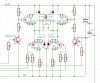
(3) My constant current approach using two transistors.

Of the three options, from a performance aspect (1) has it
From an absolute simplicity aspect (3) has it.
And (2) probably has the best compromise between the two.

Just my view.:)

spec
 
Last edited:
Hi,
Here is an H-bridge, for a forward/reverse circuit, that will power a wheelchair, it's 12v but I'm pretty sure it will work with the car, if it helps.
Camerart.
That would certainly do the job.:)

Presumably you would use one of the two approaches in post #17 above to generate the PWM signal.

spec
 
Just a further point.

Rather than having a bang bang approach to starting off and driving, it would be possible to link the accelerator to a potentiometer and have progressive speed control just like an automobile.

spec
 
Hi spec,
I think option 3 should be good enough. The small amount of wasted energy while ramping up the current is not enough to jusitfy PWM. The transistors (Or mosfets.) could just be used as switches to switch is a resisror first then apply full power after a delay. You could even have a few steps of current by switching in a few resistors. You could use a CD4017 to sequence through a few resistors befor stopping in a state with all the resistors shorted out.

Edit,
I've just read your post #19. The potentiometer together with a PWM speed controller from Ebay would probably be the easiest for the OP to implement. It may also be worth adding a circuit so full power could not be applied for about 0.5 second
Les.
 
Last edited:
Status
Not open for further replies.

Latest threads

New Articles From Microcontroller Tips

Back
Top