Continue to Site

Welcome to our site!

Electro Tech is an online community (with over 170,000 members) who enjoy talking about and building electronic circuits, projects and gadgets. To participate you need to register. Registration is free. Click here to register now.

  • Welcome to our site! Electro Tech is an online community (with over 170,000 members) who enjoy talking about and building electronic circuits, projects and gadgets. To participate you need to register. Registration is free. Click here to register now.

Bench Power Supply Peripherals

Status
Not open for further replies.

Musicmanager

Well-Known Member
Morning Guys

A couple of weeks ago I was browsing ETO when I came across a thread involving one of the 'Super Moderators' from Derbyshire extolling the virtues of Bangood.com and in particular a 0 - 30v power supply and a combined volt & ammeter display. Well, if it's good enough for him, it's good enough for me I thought, so I promptly ordered one set which has now arrived. I've since ordered another set and I've purchased a dual tap 240/24vac 250va transformer with the intention of building a dual output bench power supply.
I've noted that many of the ready made PSU's have a discreet output for 5vdc and 12vdc and there must presumably be good reason for that ? If I'm to add discreet outputs to my PSU would I be best to use Buck Converters - there are so many different schematics for buck converters on the web that seem to work in several different ways so I'm not sure which one to follow.
Anybody who is not fed up with me yet and is consequently willing to offer advice ?
Thanks
S
 
I've purchased a dual tap 240/24vac 250va transformer
That is a big chunky transformer, some would say it is overkill.

with the intention of building a dual output bench power supply.
A good idea, but there are traps and "Oooh I never thought of that" catches in there for a beginner.

many of the ready made PSU's have a discreet output for 5vdc and 12vdc and there must presumably be good reason for that ?
Yes, very good reason.
5v is a standard supply voltage for many logic integrated circuits.
12v is a general purpose supply voltage, probably originating in history because 6 cell lead acid batteries have a voltage of (about) 12volts.

If I'm to add discreet outputs to my PSU would I be best to use Buck Converters
A quick and easy solution would be to use fixed voltage three terminal linear regulators such as 7805 (5 volt) and 7812 (12volt).

JimB
 
Morning Jim

Thanks for your help.
My reasoning:-

1. Big Chunky Transformer - a friend gave me a old PSU which I managed to repair. The tranformer was very, very hot and would 'sing' after a few minutes, so I diagnosed that as the problem. I worked out a replacement would be 30v x 3 amps = 90va but someone advised adding a little to compensate for voltage regulator loss so concluded 120va was about right. Dual power supply 120va x 2 = 240va

2. Traps & ' Oh I never thought of that ' I'm keen to accept that as part of my learning curve within safety concerns and I'm sure somebody on here will point those out to me.

3. Terminal linear regulators 7805 & 7812 - Yes, I'm getting quite familiar with those IC's but I considered that on each PSU board there is a 2SD1047 & a 2SD882 both of which require a heatsink. There is also a component marked 7834 that I can't identify at the moment but looks as though it needs a heatsink.
I'm planning on a fairly large enclosure with a fan in the back but even so, I thought 2 x this little lot was probably more than enough heat. Am I being over-cautious ?

Thanks

S
 
With regard to traps for the beginner, have a look at the attached circuits.

In circuit A there are two voltage regulators driven from one AC supply.
The 0v line of the voltage regulator circuts is common to the inputs and outputs. This is ok if all you want is two 12v supplies with a common 0v line.

In circuit B the two 12v supplies are completely separate and isolated from each other, using separate secondary windings on the transformer.
With this circuit we can also connect the 0v lines together and have two 12v supplies with a common 0v.
We can also connect the +12v of one supply to the 0v of the other supply. In this case we have a + and - 12v supply with a common 0v line. This is often useful when working with op-amps.

JimB

Power Supplies.JPG
 
Hi Jim

Thanks for that information. I did some reading about positive and negative voltages and I think I nearly understand it ! Seems to me to be about considering Gnd (0v) as a mid point more than a base level - but then .. .. I think I would need to expand that knowledge quite a lot before I attempted to make use of it. I did intend to provide the 5v and 12v outlets from one sec. output of the transformer, leaving the other to power the variable, if needed. That would mean I could properly add the provision for +12v - 0v - -12v at a later date by addition rather than alteration.
Do you think my fear about heat using linear voltage regulators is unfounded ? If I'm starting with 24vdc the 5 volt particularly will generate quite a lot, won't it ? I've been reading and I got the impression that buck converters are much more efficient with much less of a heat problem. I've not yet seen or built one so I'm going by my reading alone.
Still very grateful for your help

S
 
Having looked at and thought about the circuit diagrams further, I realise I might as well do the job properly and completely first time.
Would it be best to build a separate bridge rectifier for the voltage regulator circuits or to tap off the variable PSU boards ?
Installing Circuit B is no problem but the connections to achieve 2 x 12 vdc and a common 0v and connecting +12v and 0v together to get +12v and -12v ? Are these best done externally with fly leads or internally with switches ?
I can also foresee problems with volt and ammeter readings .. .. phew, my brain aches !! lol

S
 
There is also a component marked 7834 that I can't identify at the moment but looks as though it needs a heatsink.

It's a 7824 - a 24V linear regulator, presumably (as it feeds a point marked 'fan') it's to feed an optional fan for cooling the heatsink?.

I scanned both sides of the PCB, when I get time I'm going to draw the circuit out.

I've grabbed myself a transformer today, it's got too separate 12V 4A windings, which I'm going to wire in series for the 24V - it used to power 24V soldering irons in the old workshop at work.
 
Hi Nigel

I scanned both sides of the PCB, when I get time I'm going to draw the circuit out.

Have you seen the attached ?

When I was reading the reviews on Banggood, I found a complaint from someone and this was attached to the reply.

When I start putting this together I may need your help with the ammeter connections .. ..

S
 

Attachments

  • 0-30v Power Supply.doc
    947.5 KB · Views: 385
Hi Guys

I've done some more research into negative voltage particularly from PSU, following up on JimB's suggestion yesterday. Firstly, I understand that connecting a 12vdc to 0vdc of separate outlets would give +12vdc and -12vdc, presumably the joined 'pair' would become 0vdc ? Going from pictures alone, is this often done with a small metal plate attached to the banana terminals on the outside of the enclosure ?
I still have concern about using voltage regulators along with the 2 variable power supplies because of heat. Are buck converters better or unnecessary in this instance ? I'm planning to use an ABS enclosure with a thin aluminium sheet in the base for rigidity, vent slats in the front and a 60cm fan in the back to keep it cool, but I've already experienced the vulnerability of ABS to heat !

Thanks

S
 
Hi Guys

I've done some more research into negative voltage particularly from PSU, following up on JimB's suggestion yesterday. Firstly, I understand that connecting a 12vdc to 0vdc of separate outlets would give +12vdc and -12vdc, presumably the joined 'pair' would become 0vdc ? Going from pictures alone, is this often done with a small metal plate attached to the banana terminals on the outside of the enclosure ?
I still have concern about using voltage regulators along with the 2 variable power supplies because of heat. Are buck converters better or unnecessary in this instance ? I'm planning to use an ABS enclosure with a thin aluminium sheet in the base for rigidity, vent slats in the front and a 60cm fan in the back to keep it cool, but I've already experienced the vulnerability of ABS to heat !

Yes, that's how you connect two supplies to give +/- rails - with the join as 0V.

You do of course need two separate transformers, or a transformer with two entirely separate secondary windings.
 
Hi Nigel

You do of course need two separate transformers, or a transformer with two entirely separate secondary windings.

The transformer I've got is 250VA 240/24v the outlets are marked 24 - 0 - 24 a total of 3 terminals - is that two entirely separate windings ?
 
Ah ! OK, well I got two transformers, not a problem. The second transformer has only a single winding, so I could use that and one set of the other transformer and put the 0 - 30v pcb on the other set ? That would work ?
What do you think about the heat from 2 of these 0 - 30 PCBs and some voltage regulators ? Need for caution ?

S
 
Ah ! OK, well I got two transformers, not a problem. The second transformer has only a single winding, so I could use that and one set of the other transformer and put the 0 - 30v pcb on the other set ? That would work ?

Use the 0-24 winding (ignore the 24-0 one) for one 0-30V PCB, and use the single 24V transformer for the other one.

What do you think about the heat from 2 of these 0 - 30 PCBs and some voltage regulators ? Need for caution ?

Presumably almost all the heat is from the output transistor, which needs mounting on a VERY substantial heatsink - what heatsinks are you planning using?.
 
OK, that makes sense to me, thank you.
I was also contemplating a discreet 12vdc and 5vdc terminal, largely because many of the ready made PSUs offer that facility so I guessed there is good reason for it - 5vdc is the operating voltage for most IC's and 12 vdc is general purpose, as JimB advised me yesterday, and then followed on with the ability to do - 12vdc which would be useful for Op Amps. To do that I would need 2 x discreet 12vdc to loop together as previously discussed. That means 1 x 7805 and 2 x 7812 voltage regulators running from a 24vdc input - lots of heat ?? Buck converters a better prospect ?
I'm planning an ABS enclosure with a thin aluminium sheet in the base for rigidity and a 24v 60mm fan in the back pulling air from the vent slots in the front panel.
I haven't thought about heatsinks yet, currently beyond my experience -

S
 
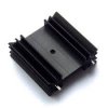
I imagine something like this will do the job.
There must be some size calculation process but google isn't giving it up yet - not asking it the right question perhaps

S
 

Attachments

  • heatsink 1.jpg
    heatsink 1.jpg
    4.5 KB · Views: 212
I've just come to an executive decision !

I'm going to build my PSU with 2 x 0 - 30vdc units ex Banggood and not bother with the discreet 5vdc and 12vdc taps until later. Maybe by the time I come to need them I will also have enough understanding to be able to install them properly.
Maybe, I'm trying to fly before I can stand up properly, never mind run !!
I will need to get one of you to help me with the ammeter connections. I'd like to have the display show the current limit but also the actual but I've no idea how to do that yet
Thanks Guys

S
 
I will need to get one of you to help me with the ammeter connections. I'd like to have the display show the current limit but also the actual but I've no idea how to do that yet

I got a combined volt/amp meter from Bangood - this will show the output voltage, and the current that's been drawn - the LED on the PCB will light to indicate current limiting is taking place.

There also 'may' be a problem with the meter I've got, in that it may require an independent (low current only) supply to run from.
 
Status
Not open for further replies.

Latest threads

Back
Top