Hi All,
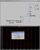
I was just trying to implement a controlled battery discharge rate calculator, as shown in the below image. A 1KHz pulse with 5% Duty Cycle is applying to a MOSFET gate. Here I got some confusion regarding the power ratings of the resistors.

1) If its a normal continuous power system, if we neglect the R1 (.01Ω,3W shunt resistor) & MOSFET's RDSon (~100mΩ), The current I = 12.8/1 = 12.8A .
The power dissipation = 12.8x12.8x1 = 144W (Bigger power rating !)
Since here a 5% duty cycle is applying, therefore for 50usec a 12.8A is passing through the resistor and rest of the time its OFF. So while considering the power ratings , whether we need to consider 12.8A x .05 = 640mA therefore P = .64 x .64 x 1 = .4096W. So in safe side just a 1W resistor is required here ? or we need to consider bigger power ratings.
2) Is it also possible to replace the 1Ω , and use the 0.01Ω(Shunt) + 0.1Ω(RDSon) for the current path. In this case, while simulating , ~150A is showing as the peak current and from the datasheet the MOSFET's Pulsed drain current is 60A. (Suppose if we are using some other MOSFET version) .
So the current will be 150A x 5% = ~ 7.5A. And power dissipation in
Shunt Resistor = 7.5 x 7.5 x .01 = 0.56W
Across MOSFET = 7.5 x 7.5 x .1 = 5.63 W
If anything wrong is found, Please correct me & give some guidance in this issue.
Thank you ...
Regards,
Geo
I was just trying to implement a controlled battery discharge rate calculator, as shown in the below image. A 1KHz pulse with 5% Duty Cycle is applying to a MOSFET gate. Here I got some confusion regarding the power ratings of the resistors.
1) If its a normal continuous power system, if we neglect the R1 (.01Ω,3W shunt resistor) & MOSFET's RDSon (~100mΩ), The current I = 12.8/1 = 12.8A .
The power dissipation = 12.8x12.8x1 = 144W (Bigger power rating !)
Since here a 5% duty cycle is applying, therefore for 50usec a 12.8A is passing through the resistor and rest of the time its OFF. So while considering the power ratings , whether we need to consider 12.8A x .05 = 640mA therefore P = .64 x .64 x 1 = .4096W. So in safe side just a 1W resistor is required here ? or we need to consider bigger power ratings.
2) Is it also possible to replace the 1Ω , and use the 0.01Ω(Shunt) + 0.1Ω(RDSon) for the current path. In this case, while simulating , ~150A is showing as the peak current and from the datasheet the MOSFET's Pulsed drain current is 60A. (Suppose if we are using some other MOSFET version) .
So the current will be 150A x 5% = ~ 7.5A. And power dissipation in
Shunt Resistor = 7.5 x 7.5 x .01 = 0.56W
Across MOSFET = 7.5 x 7.5 x .1 = 5.63 W
If anything wrong is found, Please correct me & give some guidance in this issue.
Thank you ...
Regards,
Geo