Continue to Site

Welcome to our site!

Electro Tech is an online community (with over 170,000 members) who enjoy talking about and building electronic circuits, projects and gadgets. To participate you need to register. Registration is free. Click here to register now.

  • Welcome to our site! Electro Tech is an online community (with over 170,000 members) who enjoy talking about and building electronic circuits, projects and gadgets. To participate you need to register. Registration is free. Click here to register now.

Battery Charger with auto shut-off feature

Status
Not open for further replies.
The resistor that is used in comparator circuits for hysteresis is frequently megohms. 4.7M into 15k to 47 ohms is a small amount of hysteresis. Even if the divider is 150k to 470 ohms the hysteresis is small. Try it.
 
do you have any software or sites for computing hysterysis? we have a program for this, but i'm just trying to input values, and guessing the outputs, i always come out with 110mV at ON state Vref, while the Vref at OFF state is 3.V, or larger, can't output Vreferences with 20mV or higher

are there techniques? sorry for being dumb, it's 1:50am here, and i have final quiz at 8:30am, do i need to sleep?:(
 
so mr.audioguru:

the final setup is to regulate the current into 312maH, and 4.2V

and use a 1ohm resistor for limitter, and set the Vref to 950maH * 0.03 at ON state

while at off state the Vref should be 0.2V... i'll be sleeping now, and i hope i can still review my notes in color transmitter of TV and CRT blockdiagram:(

we have only 2days left, and the other groups were finished on their prototype, while we are behind:( i wonder how god can do miracles on our circuit:confused:

thank you sir, i'll be back as soon as i wake up.
 
Keep god out of it. God might mess up your project.

Sleeping now? It is early in the afternoon here. You must be in the Soviet Union, China or India.
 
Mr.audioguru, i've realized that setting the Vref at the -feedback, and setting the Vsense at the +feedback is useless, because at NO LOAD condition, the Vsense is ZERO, which makes the comparator OFF, even there's a battery with 3V, the Vsense will be also zero, beacuse the battery is not connected to the charger, Unless there's still a Vsense eventhough the charger is not connected to the battery,

the Vsense is in between the - terminal of the battery and the limitting resistor, is there a Voltage at that point, even there's no charger connected to the battery?
 
If there is no battery in the charger then the current is zero and the charger won't begin to charge when a battery is inserted into the circuit.

So simply add a pushbutton that flips the relay so it can begin charging.
Then when the charging current drops to 10% or 3% of the battery's rating then the (+) input of the comparator is less than the reference at the (-) input and the transistor turns off the relay.
 
audioguru: Is it really possible to compute for Vref(on state) which is 22mV and a Vref(OFF state) = 0.4V, because we always come up with an equal values of Vref or the Vref for ON state is always greater than the Vref at OFF state... is it possible for the Vref at OFF state to exceed the Vref at ON state? If you don't mind sir, can we ask for your help, to compute for the resistive values needed on the inputs of the comparator.. The Vref at ON state should be 3% of 950maH, and the Vref at OFF should be 0.4(which ables the user to charge a battery with less than 3.8V, or a Vref of 0.5V, which ables to charge batteries with 3.7V or less than 3.7V... the supply voltage is 9.4V + or - 0.1V,

Note: Vref is set at the -feedback of the comparator, and the Vsense is at the +feedback
 
hi hardcore.
Can you please post a circuit showing how the components are connected, its not possible to work out the circuit from your text description and mark in the voltage points you are trying to determine.:rolleyes:
 
Your comparator is used to turn off the charging when the charging current drops to 3% of the battery's rating. Therefore the charger is off when a battery is connected to it.
You don't need to detect a Vref as high as 0.4V.

1) Will you use a 10.5V supply feeding a current regulator and a 4.2V voltage regulator in series? How much current?
2) What is the value of your current sense resistor? 1 ohm will limit the current for most of the charging time. 0.47 ohms will be better.
3) Will you use a pushbutton to start the charging?
 
ericgibbs said:
hi hardcore.
Can you please post a circuit showing how the components are connected, its not possible to work out the circuit from your text description and mark in the voltage points you are trying to determine.:rolleyes:

hello sir, please check the revised schematic...
 

Attachments

  • schematicrevised.JPG
    schematicrevised.JPG
    38.5 KB · Views: 280
audioguru said:
Your comparator is used to turn off the charging when the charging current drops to 3% of the battery's rating. Therefore the charger is off when a battery is connected to it.
You don't need to detect a Vref as high as 0.4V.

1) Will you use a 10.5V supply feeding a current regulator and a 4.2V voltage regulator in series? How much current?
2) What is the value of your current sense resistor? 1 ohm will limit the current for most of the charging time. 0.47 ohms will be better.
3) Will you use a pushbutton to start the charging?


sorry mr.audioguru for being confused on this circuit... if we put hysterysis on the comparator, there will be two Voltage References to be set on this circuit, the Vref during OFF condition, and the Vref during ON condition of the compatator...

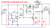
for us to charge batteries, for example, a 3.7V battery is to be charge, so to be able to charge the battery, the circuit should satisfy the Vref at OFF condition, right sir? if we need to charge a 3.7V battery, we need a Vref at OFF condition to be set on 0.4V (caused by 4.2V - 3.8V = 0.4V at 1ohm), if we charge a 4V battery(the vdrop is 0.2V which is less than 0.4V, therefore the comparator is OFF) to clarify AG, Vref are set on the -Feedback while the Vsense is at the +feedback...

and for us to charge the battery, we need the pushbutton you have suggested AG,

question: the pushbutton is connected between the 9.4V and the +feedback, if the pushbutton is pushed, the 9.4V gets into +feedback then it closes the RELAY (Vref = 0.4V) does the comparator senses the Vdrop after the pushbutton is released? if so, then the circuit will now then charge the low voltage battery..

what if we will not use a current regulator? does it take time to fully charge a nearly fully charged battery?(ex.4.1V) if not, if we lower down the 1ohm resistor to 0.5 or 0.45V, does it make faster?

please analyse also the Vref of the circuit mr.AG, the Vref at ON state is less than the Vref at OFF state( but looking at the formulas, and after experimentation on getting the necessary input resistors, Vref at ON is always greater than or equal to Vref at OFF state, in example, Vref(ON)=0.028V and Vref(OFF)=0.4V)
 
I started to update your schematic to see how you are going to make hysteresis work backwards (impossible), but then I stopped because YOU should update your schematic so we can see what you are talking about.

If you use a current-limiting resistor instead of a regulated current then the charging will take forever to reach a full charge. It will take a long time and the battery will never be completely fully charged because it is too simple.

I don't know how much is the internal resistance of a Li-Ion battery cell that causes its voltage to rise a corresponding amount immediately when it is connected to a charger. If the battery voltage is 4.1V and you try to charge it then the charger might shut off immediately.

The comparator's inputs don't work if they are within about 2V from the positive supply (input common mode voltage) so don't connect an input to the positive supply. The pushbutton should directly turn on the relay to start the charger. But then if somebody holds down the pushbutton when the battery is fully charged it will become over-charged and might catch on fire.
 
audioguru said:
I started to update your schematic to see how you are going to make hysteresis work backwards (impossible), but then I stopped because YOU should update your schematic so we can see what you are talking about.

so it is impossible to reverse the inputs for the Vsense and the Vref, because of the vref caused by hysterysis, ok... if we still use the +feedback for the Vref, and the Vsense is at the -feedback, if we have the Vref at ON condition which is the 3% of the Icharge, 0.028V, does the comparator turns ON if we will charge a 3V? given that the Vdrop is only 1.2V which is greater than the Vref at ON condition, and therefore the comparator will never turn ON at Vref of 0.028V

If you use a current-limiting resistor instead of a regulated current then the charging will take forever to reach a full charge. It will take a long time and the battery will never be completely fully charged because it is too simple.

I don't know how much is the internal resistance of a Li-Ion battery cell that causes its voltage to rise a corresponding amount immediately when it is connected to a charger. If the battery voltage is 4.1V and you try to charge it then the charger might shut off immediately.

The comparator's inputs don't work if they are within about 2V from the positive supply (input common mode voltage) so don't connect an input to the positive supply. The pushbutton should directly turn on the relay to start the charger. But then if somebody holds down the pushbutton when the battery is fully charged it will become over-charged and might catch on fire.to clarify this, once the pushbutton is pushed, or we used a SPST switch, it should be turn OFF immediately and the Relay is still ON, because on the moment of turning on the relay through a switch, a Vdrop is already sensed and will trigger the Relay permanently even the switch for turning the relay on forcedly is disconnected?

________________________________
 
I see your revised schematic now. Its hysteresis is wrong. Hysteresis is positive feedback. Yours is negative feedback.
 
audioguru said:
I see your revised schematic now. Its hysteresis is wrong. Hysteresis is positive feedback. Yours is negative feedback.

so if we put the hysterysis at the positive feedback, should the hysterysis is connected to the Vsense?

since the Vsense tends to decrease when it approaches fully charge condition, it should be connected to the +feedback and the hysterysis is connected to it?
 
Like this:

EDIT: Current sensing resistor was in the wrong spot.
 

Attachments

  • Li-Ion batt charger.PNG
    Li-Ion batt charger.PNG
    49 KB · Views: 251
Last edited:
question: mr.AG, does the Vref is set at the -feedback through R1 and R2? i'm just confused because i'm trying to compare this schematic to the attached one, why did you add another resistor at the +feedback, is it to divide the Vdrop from the current sense resistor? where is the Rh now on the circuit?
 

Attachments

  • ComparatorHyster.GIF
    ComparatorHyster.GIF
    12.1 KB · Views: 206
hardcore misery said:
question: mr.AG, does the Vref is set at the -feedback through R1 and R2?
It is not feedback. It is the reference voltage for the comparator. Select R1 and R2 to make 28.5mV plus and minus a little hysteresis.

i'm just confused because i'm trying to compare this schematic to the attached one, why did you add another resistor at the +feedback, is it to divide the Vdrop from the current sense resistor? where is the Rh now on the circuit?
Without my added resistor then the value of the R7 hysteresis resistor will be so low that it will overload the comparator's output.
 
Status
Not open for further replies.

Latest threads

New Articles From Microcontroller Tips

Back
Top