Continue to Site

Welcome to our site!

Electro Tech is an online community (with over 170,000 members) who enjoy talking about and building electronic circuits, projects and gadgets. To participate you need to register. Registration is free. Click here to register now.

  • Welcome to our site! Electro Tech is an online community (with over 170,000 members) who enjoy talking about and building electronic circuits, projects and gadgets. To participate you need to register. Registration is free. Click here to register now.

Battery Charger with auto shut-off feature

Status
Not open for further replies.
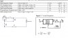
on my last reply, i did'nt noticed that the file was not attatched, but i will attatch my schematic, a revised one, after reading your last reply sir...

so to clarify things:

if the max. capacity of the battery (on terms of current) is 950maH,
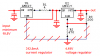
getting its 3% is equal to 28.5maH. using 4ohms as a limitter,
the voltage across this is 0.114V(28.5maH * 4ohms) and this 0.114V is divided to 2, which is equal to 57mV, and we should made a Vref of at least 57mV also? btw, are these all correct? do i need to divide the 0.114V?

question1: on the previous experiment, for example, the battery voltage to be charge is 3.7V, and the charge voltage is 4.2V, why does when we connect the battery, the voltage sensed by the comparator increases to atleast 3.8 or 3.9V, i know this is due to the charge voltage which is higher than 3.7V, but may i know how to compute for that voltage increase?

question2:eek:n the previous experiment again, when the charger tends to shut-off when the voltage sensed by the comparator reaches 4.2V(but the battery is undercharged)... on the revised circuit from which the voltage to be sense is the voltage drop on the 4ohms, do we expect in nearly fully charged condition of the battery, that if we measure the voltage across the battery in charging condition(yes this is not important, but for curiosity purposes only) the Voltage is already 4.2V?despite of the voltage to be sense by the comparator decreases until the 3% of the icharge is reached?

_________________________

we will remove the R3/R4 on the circuit, if the battery voltage is 3.6V, the voltage at the - input is 4.2V - 3.6V = 0.6V; 0.6V/2 = 0.3V
but as the battery approaches in fully charged condition,this 0.3V tends to decrease until the charging current is equal to 3% of the charge capacity, so therefore, we should not depend on the voltage of the battery under charging condition, but we should base the Vref on the 3% of current capacity. are these true?

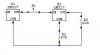
so if the Voltage drop on the 4 ohms resistor tends to decrease, i think we should put this input on the +feedback of the comparator, and the Vref will be set to the -feedback of the comparator? about the hysterysis, we should not remove this? and put also the hysterysis on the -feedback?
 
at NO LOAD condition: the Vdrop at 4ohms is 4.2V, and the voltage to sense by the comparator is 2.1V?, so if the Vref is set to the -V of the comparator(is the Vref = 114mV? or 57mV?, the current capacity is 950maH), the +feedback senses a voltage of 2.1V, then the relay will turn ON.....
if the battery voltage to be charge is equal to 3.7V, then the Vdrop is 0.5V, and the voltage to be sense is equal to 0.25V which is greater than the Vref(- feedback) the relay is still ON, and it only turns OFF when the voltage on the +feedback decreases until 114mV or 57mV...

so the Vref is equal to 114mV or 57mV(kindly clarify this sir...) to OFF the relay, and if the relay is off, is it really sure that the battery voltage across the battery is already equal to 4.2V and not undercharged? do we need to set a hysteresis on the circuit?
 
The graphs in the tutorials show that the battery is about 70% fully charged when its voltage reaches 4.2V when it is charged with a current that is 0.9 times its rated current. Then the graph shows the current slowly decreases as the battery continues to charge.

The charging current keeps decreasing because you are using a 4 ohm resistor as a current-limiter instead of using a regulated constant-current circuit like IC chargers use. Therefore charging will take a long time.

Instead of using a 4 ohm resistor you could use a 1 ohm resistor (or less) to sense the charging current and use a supply that has a constant-current regulator (850ma) followed by a 4.2V voltage regulator like IC chargers use. Then it will charge much quicker.

When the battery is fully charged then there is no load. Its charging current is very low so the voltage across the 4 ohm resistor is also very low (0.114V). That is when you want the charging to stop. The reference voltage on the comparator will be set to 0.114V.
You don't need R3 and R4 to cut the voltage to 0.057V.
 
audioguru said:
The graphs in the tutorials show that the battery is about 70% fully charged when its voltage reaches 4.2V when it is charged with a current that is 0.9 times its rated current. Then the graph shows the current slowly decreases as the battery continues to charge.

The charging current keeps decreasing because you are using a 4 ohm resistor as a current-limiter instead of using a regulated constant-current circuit like IC chargers use. Therefore charging will take a long time.

Instead of using a 4 ohm resistor you could use a 1 ohm resistor (or less) to sense the charging current and use a supply that has a constant-current regulator (850ma) followed by a 4.2V voltage regulator like IC chargers use. Then it will charge much quicker.

When the battery is fully charged then there is no load. Its charging current is very low so the voltage across the 4 ohm resistor is also very low (0.114V). That is when you want the charging to stop. The reference voltage on the comparator will be set to 0.114V.
You don't need R3 and R4 to cut the voltage to 0.057V.

so sir, if there's a load of 3.6V to be charge, therefore the charging current is 600mah, what is the effect of constant current of 850maH if the charging current limitted by the 1ohm resistor is decreasing from 850maH to 100maH(if the voltage is 4.1V, so it only depends on the limiting resistor?, if i set the constant current to 500maH, and i used a current limiter of 1ohm, and the battery voltage to be charge is only 3.6V, then the Vdrop is 0.6V and supposed to charge the battery at 600maH, and because the constant current is set to 500maH, then what would be the effect?

EDITED: or at constant current of 850maH, even there's a current limiter of 1ohm, whenever the battery voltage is 4V, the charging current is still 850maH? and not 200mah?
 
Last edited:
in reference to the schematic, a LM317 is used as the voltage regulator(4.2V) on m schematic is correct? i used a 1.5ohms for current regulation of 833maH.

but on the MAX1551 datasheet, it supplies between 220 to 340maH, so should i use atleast 300maH as a constant current? and use a 1ohm resistor as the current limitter?
 

Attachments

  • powersupply.JPG
    powersupply.JPG
    50.6 KB · Views: 403
The constant current supply will try to make the current constant. But if the 1 ohm resistor has only 0.2V across it because the battery has charged to 4.0V then the resistor limits the current to (4.2V - 4.0V)/1= 0.2A.

Battery charger ICs use a current-sensing resistor that is outside the voltage and current feedback so it doesn't limit the current. It is too complicated for your simple circuit.

That is why I said, "use 1 ohm or less". If the resistor is less than 1 ohm then it limits the current less. But then sensing voltage will be very low and the input offset voltage of the comparator will cause poor accuracy.
 
audioguru said:
The constant current supply will try to make the current constant. But if the 1 ohm resistor has only 0.2V across it because the battery has charged to 4.0V then the resistor limits the current to (4.2V - 4.0V)/1= 0.2A.

Battery charger ICs use a current-sensing resistor that is outside the voltage and current feedback so it doesn't limit the current. It is too complicated for your simple circuit.

That is why I said, "use 1 ohm or less". If the resistor is less than 1 ohm then it limits the current less. But then sensing voltage will be very low and the input offset voltage of the comparator will cause poor accuracy.

so is it ok to use only a 1ohm current limiter, eventhough the current is not constant? so at 3% of the Icharge , the Vref is only 28.5mV.

on the hysterysis of the circuit, do we still need them?
 
You can make an LM317 a current regulator with one resistor.
You can make an LM317 a voltage regulator with two resistors.
But it makes a lousy voltage and current regulator with three resistors.

Try it. Load your LM317 circuit to 500mA. Its output voltage is only 1.7V.
Its output voltage is 4.18V when it doesn't have any load current.

You need an LM317 as a current regulator followed by another LM317 voltage regulator. Their minimum input voltage is 10.5V for a 4.2V output voltage.
 
Using a 1 ohm resistor as a current limiter and sensor works but it increases the charging time a lot. It will take forever for the battery to fully charge.
Maybe you can cheat if your teacher isn't reading this.

Read on the datasheet for any comparator about how it oscillates at a very high frequency when its inputs reach the threshold voltage without hysteresis. It might burn out or wear out the relay.
 
it has constant current of 312.5maH, and a voltage of 4.18V, is it correct now sir?, and i will use a 1 ohm resistor as limitter? what if the battery voltage is 3.6V, then the Vdrop is 0.6V, now what is the charging current? is it 600mah? or the constant current of 312.5maH?
 

Attachments

  • supply.JPG
    supply.JPG
    7.1 KB · Views: 263
how about on my previous post? is it correct to put the Vref at the -feedback of the comparator? because the sensing voltage tends to decrease as it approaches a fully charged condition?
 
On the actual defense:
1.we will be charging 3 batteries at the same time, to show the multi-charging feature of the charger...

2.we will charge a battery with at least 4V to 4.1V to show the auto shut-off feature of the battery.

i think the panel of judges will not wait to charge a low voltage battery, because we will tell them that it will take a long time to fully charge the battery(ies).

but we have the statistics on the documentation, and we need to know the charging time of the charger:(

EDITED: it's also important that when the charger shuts off, the battery voltage should be 4.2V.
 
Last edited:
hardcore misery said:
is it correct now sir?
You missed many important things.
I am not a SIR because I have never been near The Queen of England.
I have also never been to India.
Call me Audioguru or Hey You.

i will use a 1 ohm resistor as limitter? what if the battery voltage is 3.6V, then the Vdrop is 0.6V, now what is the charging current? is it 600mah? or the constant current of 312.5maH?
If the power supply is regulated at 312.5mA then how can it supply more current??
When the battery voltage reaches 4.0V then the 1 ohm resistor limits the current to omly 200mA. At 4.1V then the current is limited to only 100mA.

we will be charging 3 batteries at the same time, to show the multi-charging feature of the charger
Your circuit will charge only one Li-Ion battery cell. Each cell will have a different amount of charge remaining. Each cell will need its own amount of charging time and will need its own charger circuit.
 

Attachments

  • current and voltage regulators.PNG
    current and voltage regulators.PNG
    17.4 KB · Views: 262
audioguru said:
You missed many important things.
I am not a SIR because I have never been near The Queen of England.
I have also never been to India.
Call me Audioguru or Hey You.


If the power supply is regulated at 312.5mA then how can it supply more current??
When the battery voltage reaches 4.0V then the 1 ohm resistor limits the current to omly 200mA. At 4.1V then the current is limited to only 100mA.


Your circuit will charge only one Li-Ion battery cell. Each cell will have a different amount of charge remaining. Each cell will need its own amount of charging time and will need its own charger circuit.


sorry mr.audioguru for calling you SIR, it's because we treat you as an educator, and all of our educator is called b Sir.(insert name here)

btw, our transformer is only 9V/3A, but using LM317, it can go beyond 9.7V. so mr.audioguru, does it take a long time to fully charge a 4V or 4.1V with these set-up?
 
If the unregulated power supply source is not about 10.5V then the LM317 IC might not regulate properly.

Look at the graphs and guess how long your circuit will take to charge.

Look at the graph and guess at what percentage of a full charge will occur if you stop the charging when the current is 10%.

It is easy to calculate a simple voltage divider to reduce 8.8V down to 0.028V. 15k to 47 ohms gives 0.0275V.
 
audioguru said:
If the unregulated power supply source is not about 10.5V then the LM317 IC might not regulate properly.

Look at the graphs and guess how long your circuit will take to charge.

Look at the graph and guess at what percentage of a full charge will occur if you stop the charging when the current is 10%.

It is easy to calculate a simple voltage divider to reduce 8.8V down to 0.028V. 15k to 47 ohms gives 0.0275V.

its easy to compute without hysterysis..
 
Status
Not open for further replies.

Latest threads

New Articles From Microcontroller Tips

Back
Top