Continue to Site

Welcome to our site!

Electro Tech is an online community (with over 170,000 members) who enjoy talking about and building electronic circuits, projects and gadgets. To participate you need to register. Registration is free. Click here to register now.

  • Welcome to our site! Electro Tech is an online community (with over 170,000 members) who enjoy talking about and building electronic circuits, projects and gadgets. To participate you need to register. Registration is free. Click here to register now.

Battery Charger with auto shut-off feature

Status
Not open for further replies.
audioguru said:
hardcore misery said:
question: mr.AG, does the Vref is set at the -feedback through R1 and R2?
It is not feedback. It is the reference voltage for the comparator. Select R1 and R2 to make 28.5mV plus and minus a little hysteresis.


Without my added resistor then the value of the R7 hysteresis resistor will be so low that it will overload the comparator's output.


private message sent..
 
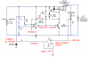
mr.AG please confirm if the schematic is now correct...

the Vref of the -input was set to 31mV

the hysterysis was used at the +input, so that if the voltage drop is 0.0575, at 4.13V, the charger shutts off then the Vinput(2.13mV is lower than 31mV)at the +V will decrease to 1.21mV due to not charging condition...

so the pushbutton will serve as a trigger for the comparator to charge the battery, once the pushbutton connects the relay, the Vdrop is sensed at the +input and the comparator turns ON, then the pushbutton must released, in other words, the pushbutton is pushed quickly,, we can you toggle switch mr.AG? toggle the switch ON, then switch again it to OFF.. are these correct?
 

Attachments

  • schematicrevised.JPG
    schematicrevised.JPG
    29.2 KB · Views: 1,032
Remove the capacitor at the (+) input of the comparator. You want the hysteresis to change the voltage here as fast as possible.

Hysteresis? There won't be any hysteresis because the output saturation voltage of the comparator is about +120mv so it never goes low enough to trip the hysteresis.

I fixed it:
1) I added an opamp to amplify the 28.5mV from the 1 ohm current sensor to +410mV. +410mv is halfway between +120mV and +700mV.
2) The reference voltage for the comparator should be +410mV.
3) I added a diode at the output of the opamp to limit its output to +700mV.

The LM358 opamp is a dual opamp. Use the other half as the comparator.
 

Attachments

  • LM339 output saturation voltage.PNG
    LM339 output saturation voltage.PNG
    14.7 KB · Views: 682
  • Li-Ion batt charger.PNG
    Li-Ion batt charger.PNG
    65.3 KB · Views: 8,400
audioguru said:
Remove the capacitor at the (+) input of the comparator. You want the hysteresis to change the voltage here as fast as possible.

Hysteresis? There won't be any hysteresis because the output saturation voltage of the comparator is about +120mv so it never goes low enough to trip the hysteresis.

I fixed it:
1) I added an opamp to amplify the 28.5mV from the 1 ohm current sensor to +410mV. +410mv is halfway between +120mV and +700mV.
2) The reference voltage for the comparator should be +410mV.
3) I added a diode at the output of the opamp to limit its output to +700mV.

The LM358 opamp is a dual opamp. Use the other half as the comparator.

what about the revised schematic i've posted above, is it not impossible to use that circuit? FYI mr.AG it's already 1:00am here and our final defense starts on 11:00am, all electronics shops are closed now, its midnight here... so the pushbutton on the revised circuit iv'e posted is now useless? and the circuit itself is useless? the only way for us to pursue your schematic is for us to request a reschedule of our final defense of my group only, or to move it in the afternoon, if we are lucky that our prof. granted our request, that's good for us, BUT this schematic you've suggested is really a 100% working? if then, we will try our luck to make a request to our prof..:(
 
audioguru said:
Remove the capacitor at the (+) input of the comparator. You want the hysteresis to change the voltage here as fast as possible.

Hysteresis? There won't be any hysteresis because the output saturation voltage of the comparator is about +120mv so it never goes low enough to trip the hysteresis.

I fixed it:
1) I added an opamp to amplify the 28.5mV from the 1 ohm current sensor to +410mV. +410mv is halfway between +120mV and +700mV.
2) The reference voltage for the comparator should be +410mV.
3) I added a diode at the output of the opamp to limit its output to +700mV.

The LM358 opamp is a dual opamp. Use the other half as the comparator.

do we still need a pushbutton for this circuit? if i will use a TL072, or a JRC4560, are there changes on the voltages? if it is given that we pursued your schematic, can we have the computations and formulas used on your schematic( and a lot of changes on the documentation should be fixed )
 
I don't know if my schematic works. If I want a battery charger then i simply use a battery charger IC that works perfectly.

I used an LM358 opamp because it s inputs work at 0V and its output goes down almost to 0V.
The inputs of a TL072 stop working below about 2.5V. Its output goes down only to 1.2V. I couldn't find the datasheet for the Japanese dual opamp.

Try your latest circuit without the 0.1uf capacitor and without the hysteresis feedback resistor. It might work or the comparator might oscillate when it reaches the threshold.

Any of these circuits need the pushbutton to start them.
 
tried the circuit, it only lights up the LED and does not turn ON the Relay, (that is when i connect the 9.4V to the GND, but connecting the collector to the emitter won't turn on the comparator
 
hardcore misery said:
tried the circuit, it only lights up the LED and does not turn ON the Relay, (that is when i connect the 9.4V to the GND, but connecting the collector to the emitter won't turn on the comparator
Which circuit?
When the pushbutton shorts the transistor then LED should light and the relay should turn on. The relay should stay on when the pushbutton is released if there is a Li-Ion battery charging in the circuit.
 
if the battery is in the cellphone when the battery is being charged, you need the charger for that phone and it does it automatically, i assume, because i upgrade to another phone 3 times, and they all did it automatically
 
Guys I really need your help with something here if you can,
I need to adjust this circuit so that it will work on charging a 7AH battery (cealed) now the thing is i read that the vcc for NE555 can be 16 V so I am planning on supplying this circuit with 14v DC so that I can use it for charging the 7AH 12 V battery, i must change the zener to a more value but i need more current for charging I think 800 ma is enough , what do you think could I do that with a triac instead of using the transistor in the diagram ?
could anyone give me a solution by changing some compenonts in the circuit to fix this problem
 

Attachments

  • Cir-01-mobile-charger.pdf
    60.8 KB · Views: 515
Hi Adrian,
You attached a charger circuit that is 100 years old. Cell phones stopped using Ni-Cad batteries many years ago.

It charges a Ni-Cad battery, not a sealed lead-acid battery.
 
No, as audioguru has already stated, it's designed for Nicads and not lead acids.
 
Status
Not open for further replies.

New Articles From Microcontroller Tips

Back
Top